Airport Junction Box & Transformer Housing
The physical infrastructure of AGL: L-867 and L-868 light bases, cable entry, drainage, connectors, loading, frangibility, installation, inspection and maintenance.
Junction Boxes, Transformer Housings & Light Bases
The physical infrastructure that supports and protects AGL equipment.
These components provide mounting, cable entry, transformer accommodation, electrical connections and mechanical protection for airport lighting equipment. Design must account for the lighting application, aircraft and vehicle loading, installation depth, pavement construction, cable routing, drainage, corrosion, connector access, maintenance, alignment, environmental exposure and frangibility where applicable.
In FAA terminology, Type L-867 bases suit airport light fixtures, transformer housings and junction boxes subject to occasional light-vehicle loading. Type L-868 bases suit in-pavement fixtures, series-circuit transformer housings and junction boxes subject to aircraft and other heavy-vehicle loading. The governing specification is FAA AC 150/5345-42K (30 September 2024), which the FAA lists as Active.
Light base
The mounting interface for a fixture, and often also transformer housing and junction box.
Transformer housing
Physically accommodates the isolation transformer. The transformer does the electrical work.
Junction box
A protected location for cable connections and maintenance access.
Junction Box, Transformer Housing & Light Base
The three functions often overlap in one component.
Airport junction box
A protected enclosure or base for electrical cable connections. May route primary and secondary cables, hold connection points, accommodate isolation transformers and give maintenance access.
Transformer housing
The enclosure or base accommodating an AGL isolation transformer: mechanical and environmental protection, cable entry, transformer positioning, connector and maintenance access.
Airport light base
The physical mounting interface for a fixture. Depending on type it also serves as transformer housing, junction box and cable connection point.
FAA Type L-867 is specified for use as a light-fixture mounting base, transformer housing and electrical junction box. A junction box in an AGL circuit may sit in the path CCR → primary cable → junction / connection point → isolation transformer → secondary cable → fixture, and may contain cable terminations, transformer, connectors, cable loops, grounding connections, fixture connections and spare cable.
Runway
- Edge, threshold, end
- Centreline
- Touchdown zone
Taxiway
- Edge, centreline
- Stop bars
- Runway guard lights
Approach and other
- Approach light connection points and series transformers
- Selected signs and visual aids
- Ancillary equipment connection points
The sealed box where the primary cable of a series loop is connected through — kept dry, earthed, labelled and ready to isolate for testing.
AGL Visual Encyclopedia: A series-circuit junction box Transformer housing Fixture housing
L-867 vs L-868 (and L-894, L-895)
The major distinction is the loading environment, not the electrical function.
| FAA type | Primary application | Loading |
|---|---|---|
| L-867 | Light base, transformer housing, junction box; direct earth burial with or without concrete backfill | Occasional light vehicular loading, no aircraft or heavy vehicles |
| L-868 | Base for in-pavement light fixtures, housing for series-circuit transformers, junction box. Must accept any in-pavement fixture certified to AC 150/5345-46 | Aircraft and other heavy vehicular loading |
| L-894 | Elevated light cover (baseplate) mounting on an L-867 base | Non-load-bearing |
| L-895 | Elevated light stake mounting | Elevated-light application; Class IA only |
Which base type does the application point to?
A first-pass guide following the FAA type definitions. The approved airport design always governs.
An L-867 and an L-868 must not be treated as interchangeable just because they may share electrical functions. The mechanical loading environment is different, and installing an L-867 where a heavy-load L-868 is required is a basic selection error.
Material Classes and Base Sizes
State the class and size in any specification.
Class IA
Metal construction in exact conformance to the critical dimensions and requirements for standardization between parts.
Class IB
Class IA requirements plus corrosion testing showing resistance to deicing fluids containing potassium acetate.
Class IIA
Non-metallic construction meeting the same dimensional and performance requirements.
Class IIB
Non-metallic construction plus the potassium acetate corrosion resistance testing.
| Size | Nominal diameter | Applicable types |
|---|---|---|
| A | 8 in / 203 mm | L-868 |
| B | 12 in / 305 mm | L-867, L-868, L-894 |
| C | 15 in / 381 mm | L-868 |
| D | 16 in / 406 mm | L-867, L-894 |
| E | 24 in / 610 mm | L-867 |
The buried housing under a light, and the first place AGL meets the civil works: it is built into the pavement, so everything about it has to be agreed on site.
AGL Visual Encyclopedia: A base can
Shallow and Deep Bases
Engineering terms, not FAA type designations.
"Shallow base" and "deep base" describe physical installation arrangements and should not be confused with L-867 / L-868. Depth and configuration depend on fixture type, pavement thickness, cable routing, transformer size, installation depth, drainage, structural requirements, maintenance access and project drawings. A deeper base gives more volume for transformers and cable routing; a shallower one suits restricted depth. Selection follows the approved installation design.
The buried housing under a light: it carries the fixture, takes the cables in, shelters the transformer and keeps the whole assembly dry.
AGL Visual Encyclopedia: A base-can arrangement
In-Pavement and Elevated Light Bases
Different exposure, different base.
In-pavement base (L-868)
Supports fixtures flush or substantially flush with the pavement, exposed to aircraft wheel loads, heavy vehicles, pavement movement, water, deicing chemicals and temperature cycling. Must give a stable, accurately aligned interface.
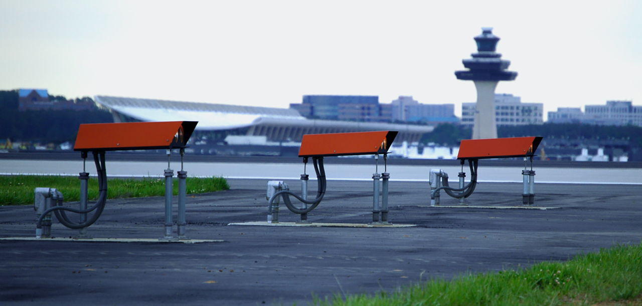
Elevated base (L-867 + L-894)
Mounts an elevated fixture via an L-867 base and an L-894 cover/baseplate, providing fixture support, bolt interface, transformer receptacle positioning, drainage and a frangible connection interface.
The small concrete base under an elevated light. It sets the fixture’s position, height and facing, so it has to be right before the concrete cures.
AGL Visual Encyclopedia: A fixture foundation

Load Environment and Certification Testing
Selection is by loading, not only electrical function.
L-867: 250 psi
Certification load test applied uniformly through a rubber block, three loadings, no permanent deformation, cracking or bolt-torque loss.
L-868: 450 psi
Same method at 450 psi for the aircraft and heavy-vehicle environment; also fatigue, impact and flange bolt torque tests where non-A36 materials are used.
L-894: 2,500 lb
Static compressive load, with a bending moment of 2,500 ft-lb for L-804 and 700 ft-lb for other applications.
Certification includes weld-integrity (air-pressure leakage), dimensional, coating-thickness and visual tests, a 21-day potassium acetate test at 194 °F (90 °C) for Class IB/IIB, a temperature-shock test for non-metallic Class II, and torque tests for adjustable L-868 bases. Production lots are sampled to ANSI/ASQ Z1.4 at AQL 2.5. The 2024 revision added corrosion-prevention considerations and new load-test requirements.
"Fits the fixture" does not mean "is an approved replacement". A visually similar base can differ in wall thickness, flange geometry, material, strength, corrosion protection, connector interface and load performance.
Airfield lights live where aircraft operate. Blast pushes sideways on elevated lights, and wheels press down on every inset light. Pick a condition to see what each does.
AGL Visual Encyclopedia: How do jet blast and wheel loads damage fixtures
Cable Entry, Conduit and Routing
Entry must avoid bending, abrasion, water traps and connector strain.
Entry options
Bottom, side or conduit entry, or direct-buried cable, for primary series-circuit and secondary fixture cable. Standard bases have two conduit entrances near the bottom; number, type, size and location can be varied to project needs.
Conduit connections
Coordinate with wall thickness, cable size, bend radius, sealing, drainage and corrosion protection. Sharp edges inside the body must be removed to prevent cable chafing.
Routing inside the base
Keep cable from preventing fixture seating, damaging connectors, interfering with the transformer, making sharp bends, being trapped under a cover or retaining water. Provide slack where the approved procedure requires it.
Do not drill or modify a certified light base casually. Modifying a standard certified component makes it non-standard and voids certification. The AC's only exceptions are cutting additional conduit holes during installation and installing threaded inserts in the upper flange, because they do not affect structural integrity. Even then, cutting must be supervised by the Construction Manager and corrosion protection applied as directed. Coatings only work while the surface is unbroken.
The buried conduits that carry AGL cable across the airfield. They are laid with the civil works, so the route, depth and spare ways have to be agreed before the trench closes.
AGL Visual Encyclopedia: Cable ducts Cable installation
Connector Arrangement and Access
Connections should stay serviceable without dismantling unrelated equipment.
Connector interfaces follow the L-823 plug and receptacle specification (AC 150/5345-26). For elevated mounting, the transformer receptacle (typically L-823 Class A, Type II, Class 8) must be positioned so its mating face is at the yield point and will not be dislodged by separation from the plug, with drainage below the yield point so no water builds above the mating surface.
The base needs working space for connector installation, transformer replacement, cable inspection, electrical testing, cleaning and fault diagnosis. Poor access can turn a simple transformer swap into a major maintenance operation.
The few points on a series circuit where cables are joined: at each transformer, out to each light, along the cable, and at the regulator.
AGL Visual Encyclopedia: Where are the connector locations
Drainage in Airport Light Bases
Good base design = electrical protection + mechanical protection + drainage.
The conduit/base system should have drains at low points so water and deicing fluids drain away. If a drain is specified it is provided in the bottom of the base; if not specified, it should be 3/4 in (19 mm) in diameter. If water and deicing fluids pool for long periods, corrosion of the conduit and base system accelerates.
What standing water causes
- Corrosion and accelerated metal degradation
- Connector deterioration
- Cable insulation damage
- Transformer problems and ground faults
- Intermittent lighting
Surface water protection
- Grooved spacer ring with O-ring gasket seals the fixture/base interface on L-868
- Protective dam stops grout or sealant sealing the fixture in place
- Elevated covers are flat or sloped to drain
Installation
- Plan drainage before concrete placement
- Light base → low point → drain → drainage path
- Keep water from the transformer, connectors, cable, flange and fixture interface
If water is found in a base, determine why before just removing it. Persistent water usually indicates a drainage, sealing or environmental problem.
Letting water leave a light base can instead of collecting in it — a drain hole, a free-draining bed below and a drain pipe laid to a fall — so the transformer and connectors are not left standing in water.
AGL Visual Encyclopedia: Base-can drainage Water ingress prevention
Spacer Rings, Extensions, Level and Azimuth
The base sets the physical reference for the fixture.
| Accessory | Function |
|---|---|
| Flat spacer ring | Height adjustment for L-867 or L-868 |
| Grooved spacer ring | With an O-ring gasket, seals the in-pavement fixture to the base against surface water (L-868) |
| Beveled spacer ring | Level and/or height correction for out-of-level bases |
| Azimuth correction spacer ring | Corrects the alignment of fixtures on misaligned L-868 bases |
| Adapter ring | Converts an existing base bolt circle to a different fixture bolt circle, with at least 1/2 in thread engagement |
| Base extension | Height adjustment when spacer rings cannot reach it; minimum length 1-3/4 in (L-867) or 2-1/4 in (L-868) |
A maximum of three rings may be stacked, and stacked height should not exceed 2.25 in (57 mm); beyond that, use an extension. A base that is tilted, rotated, mislocated or at the wrong elevation causes problems with aiming, fixture alignment, photometric performance, pavement interface, drainage and mechanical fit — especially for centreline, directional, approach and PAPI-related fixtures.
Pointing the light where the design says — the fixture’s index mark brought onto a line parallel to the runway axis, the fixture levelled, then locked and re-checked after the bolts are torqued.
AGL Visual Encyclopedia: Fixture alignment at installation
Frangibility Considerations
Evaluate the base together with the complete fixture mounting assembly.
L-894 baseplates mate with a male-threaded frangible device. The height to the frangible-device breakpoint, once threaded into the baseplate, must be no higher than 3 inches above the surrounding grade (per AC 150/5300-13), and the hub height must comply with AC 150/5345-46 and AC 150/5220-23. Standard thread sizes are 1-1/2 in × 12 UNF and 2 in × 11.5 NPT/NPS. A neoprene gasket (nominal 1/8 in) seals cover to base, and the cover needs a ground lug or bolt for at least #6 AWG.
The L-895 stake alternative uses 2 × 2 × 3/16 in steel angle, 30 in long as standard; L-804 fixtures must not be stake mounted.
Fitting an elevated fixture so it stands in normal use but breaks away cleanly if struck — the right coupling at its designed break point, nothing added to stiffen it, and a lead that lets go.
AGL Visual Encyclopedia: Frangible mounting at installation
Materials, Corrosion Protection & Grounding
Corrosion protection
Ferrous parts must be treated. Class I bases, extensions and rings thicker than 1/4 in are hot-dip galvanized (ASTM A123); thinner plates and rings are zinc plated (ASTM B633) or galvanized. Zinc-dust primer touch-up must not exceed 10% of the treated area.
Bolts
Per EB 83A: 18-8 stainless steel typical, coated steel permitted. Anti-seize is recommended for stainless bolts and is not supplied by the base manufacturer.
Grounding
Each base has an internal and external ground strap connected to a ground lug. Never use an exothermic weld on a galvanized base: heat damages the zinc coating and field repair is usually ineffective.
Appropriate separation material is required between dissimilar metals to prevent galvanic action. Coating damage from drilling, welding or cutting accelerates corrosion of the exposed steel, so field modifications must be controlled and corrosion protection restored.
Connecting the exposed metal of AGL equipment to earth, so a fault that energises a case sends current to ground instead of through whoever touches it.
AGL Visual Encyclopedia: Equipment earthing
Airport Light Base Installation
Follow approved drawings and manufacturer instructions.
Prepare
Build
Verify
Elevation: the base top must relate correctly to finished pavement or ground. Errors leave the fixture proud of or below the pavement, trap water, cause vehicle-load problems, distort optical geometry and complicate maintenance. Concrete: follow the approved civil and electrical design for base position, concrete grade, compaction, reinforcement, drainage, movement, finished elevation and pavement interface; do not support the base so loads transfer contrary to the design.
Setting the housing that carries a light fixture into the pavement — in the right place, level, flush, aligned and fully grouted — so the fixture bolts on correctly and stays there under traffic.
AGL Visual Encyclopedia: Base-can installation Base-can grouting
Inspection and Maintenance
Preserve the original structural and environmental characteristics of the base.
Structure
- No cracks or deformation
- No severe corrosion
- Cover and bolts secure
Electrical
- Primary and secondary connectors intact
- Cable insulation and transformer condition
- Grounding intact
Drainage and environment
- Drain clear, no standing water
- No mud, debris or chemical build-up
- No water ingress
Alignment
- Fixture correctly positioned
- Base level and azimuth acceptable
- Pavement interface acceptable
Transformer Housing Inspection & Maintenance
Transformer
- Correct transformer installed, rating as designed
- Transformer position and physical security
- Case condition
Connections and routing
- Primary connectors inspected
- Secondary connector inspected
- Cable routing checked, no connector strain
Water and housing
- Water accumulation and internal contamination
- Drainage and corrosion checked
- Housing condition
After the checks, confirm fixture operation and perform photometry where required.
Routine maintenance includes cleaning, connector and bolt inspection, gasket replacement, corrosion treatment, drainage inspection, transformer replacement, fixture realignment, cover replacement and cable inspection.
A close look at the buried housing that holds an airfield light, checking the flange, grout, wall, drain and connector for water, corrosion, movement and damage before they become a fault. A base can hides most of its problems below the pavement.
AGL Visual Encyclopedia: Base-can inspection
Common Failures
Tap a card for possible causes.
Water accumulation
Possible causes
- Blocked drainage
- Poor drainage design
- Surface-water entry
- Damaged gasket
- Incorrect installation
Corrosion
Possible causes
- Standing water
- Damaged coating
- Deicing chemicals
- Soil exposure
- Dissimilar-metal contact
Broken cable
Possible causes
- Mechanical damage
- Excessive tension
- Poor routing
- Construction activity
Connector failure
Possible causes
- Poor connection
- Water ingress
- Mechanical damage
- Incorrect installation
- Contact deterioration
Transformer movement
Possible causes
- Poor installation
- Cable tension
- Inadequate support
Light base problems
Possible causes
- Misalignment and settlement
- Cracked components, damaged flange
- Loose bolts
- Incorrect elevation
- Damaged gasket or drain
- Pavement interface deterioration
Mechanical base problems can ultimately affect lighting reliability and, in some cases, photometric performance.
Fogged lenses, water standing in a can, and insulation resistance that drifts down test after test — the slow warning that comes before the earth fault.
AGL Visual Encyclopedia: What does moisture ingress look like
Troubleshooting Through the Housing
Follow the complete electrical chain.
Start at the fixture and work back: is the secondary connector intact, is the transformer healthy, are junction-box connections intact, is the series circuit continuous, is the CCR delivering the required current? The chain is CCR → primary cable → junction / transformer housing → transformer → secondary connector → fixture.
The symptom shows whether the primary, the secondary or the insulation failed, and a short set of continuity, insulation and visual checks confirms it.
AGL Visual Encyclopedia: How do you troubleshoot an isolation transformer
Replacing an Airport Light Base
| Step | Action |
|---|---|
| 1. Identify the existing base | Record type, class, size, fixture, application and loading condition |
| 2. Find the cause of failure | Corrosion, settlement, vehicle damage, water, incorrect installation or pavement movement |
| 3. Select the replacement | Match type, size, class, fixture interface, load and environmental requirements |
| 4. Reinstall | Maintain location, elevation, alignment, drainage and cable routing |
| 5. Test | Mechanical condition, electrical connection, fixture operation, alignment, photometry where applicable |
The circuit is made safe, the right type and rating is chosen, the old unit comes out and the new one is fitted, and nothing is energised until insulation and continuity have been tested and the change recorded.
AGL Visual Encyclopedia: A transformer replaced
Selection Checklists
| Parameter | Question |
|---|---|
| Application | Runway, taxiway, approach, elevated or in-pavement? |
| Loading | Light vehicle, heavy vehicle or aircraft? |
| Base type | L-867, L-868 or other approved type? |
| Size and flange | Correct diameter, flange and fixture interface? |
| Circuit and transformer | 6.6 A, 20 A or other; which transformer type and rating? |
| Cable and connector | Primary and secondary arrangement, approved connectors, grounding provision |
| Drainage | Where does water drain? |
| Environment | Temperature, chemical exposure, corrosion resistance, deicing-fluid resistance |
| Maintenance | Can the transformer and connectors be accessed easily? |
| Certification | What approval does the project or authority require? |
Use an L-867 arrangement when
- Occasional light-vehicle loading applies
- Mounting an elevated airport light
- A transformer housing or junction box sits outside aircraft or heavy-vehicle areas
- The approved design specifies it
Use an L-868 arrangement when
- Lighting is in-pavement
- Aircraft or heavy vehicles can impose loads
- The approved design requires the higher-load base
Standards and Applicability
FAA AC 150/5345-42K — Specification for Airport Light Bases, Transformer Housings, Junction Boxes, and Accessories (30 September 2024; FAA status Active; it cancels 42J). It covers light bases, transformer housings, junction boxes, accessories, elevated light covers and stakes, and sets type, class, size, dimensions, materials, protective coatings, fabrication, load testing, qualification and production testing. Only equipment meeting it is listed in AC 150/5345-53 six months after the issue date.
Use is mandatory for projects funded under federal grant programs including AIP, and for PFC-funded projects, and recommended for other airport operators. L-867 and L-868 are FAA designations: the applicable standard at an airport depends on the governing aviation authority and project requirements. Related references: AC 150/5345-26 (L-823 connectors), AC 150/5345-46 (fixtures), AC 150/5340-30 (visual aid installation details), AC 150/5220-23 (frangible connections), EB 83A (in-pavement fixture bolts).
8 Common Installation Mistakes
1. Wrong base type
An L-867 where an L-868 heavy-load base is required.
2. Poor drainage
Water trapped around the transformer and connectors.
3. Incorrect elevation
Fixture too high or too low relative to the pavement.
4. Poor alignment
Base installed at the wrong azimuth.
5. Damaging the protective coating
Cutting or drilling without restoring corrosion protection.
6. Connectors under tension
Incorrect connector routing.
7. Ignoring access
Transformer or connectors where maintenance is needlessly hard.
8. Treating the base as generic hardware
Using an unapproved enclosure chosen only on dimensions.
More Than an Enclosure
A junction box or transformer housing is not a generic outdoor box. AGL components may need to satisfy aircraft and vehicle loading, frangibility, pavement and buried installation, water exposure, deicing chemicals, connector systems, standardized dimensions and fixture mounting. They form the physical interface between civil infrastructure, electrical infrastructure, AGL equipment, maintenance access and environmental protection.
Select the correct base. Protect the circuit. Control water. Maintain alignment. Preserve the approved installation.
Explore the AGL Engineering Knowledge Hub
Fundamentals
Standards & Compliance
Runway, Taxiway & Approach Lighting
Surface Movement & Safety
PAPI
Electrical Engineering & Power
Photometry & Testing
Maintenance, Inspection & Safety
Resources, Documentation & Careers
Frequently Asked Questions
Q1What is an airport junction box?
A protected enclosure for electrical connections that, depending on application, may also serve as a transformer housing or light-fixture mounting base.
Q2What is an AGL junction box?
A junction enclosure specifically intended for Airfield Ground Lighting electrical connections and associated components.
Q3What is an airport transformer housing?
A protected physical location for an AGL isolation transformer and its associated cable connections.
Q4What is an airport light base?
A structural mounting component that supports airport lighting fixtures and may also function as a transformer housing or junction box.
Q5What is an L-867 light base?
An FAA base type for airport light fixtures, transformer housings and electrical junction boxes subject to occasional light-vehicle loading but no aircraft or heavy vehicle loading.
Q6What is an L-868 light base?
An FAA base type for in-pavement airport light fixtures, series-circuit transformer housings and junction boxes subject to aircraft and other heavy-vehicle loading.
Q7What is the difference between L-867 and L-868?
The loading environment. L-867 is for occasional light-vehicle loading; L-868 is for aircraft and heavy-vehicle loading. Certification load tests are 250 psi and 450 psi respectively.
Q8Can an L-867 be used for an in-pavement runway light?
Not automatically. The type must follow the approved design and loading requirements. FAA identifies L-868 for in-pavement fixtures subject to aircraft or heavy-vehicle loading.
Q9What is an airport light base drain?
A drainage provision that lets water and other liquids leave the base and conduit system instead of pooling around cables, transformers and connectors.
Q10Why is drainage important in AGL bases?
Standing water can accelerate corrosion and contribute to electrical and connector problems. The FAA specification calls for drains at low points in the base and conduit system.
Q11Can an airport light base be drilled on site?
Only per the approved installation procedure. Modifying certified components makes them non-standard and voids certification, except for additional conduit holes and threaded inserts in the upper flange, with supervision and corrosion protection.
Q12What is an L-894?
An FAA designation for a non-load-bearing elevated light cover (baseplate) that mounts on an L-867 light base.
Q13What is an L-895?
An FAA designation for an elevated light stake mounting, used when an elevated fixture is not installed on a light base.
Q14What do Class IA, IB, IIA and IIB mean?
IA and IB are metal; IIA and IIB are non-metallic. The B classes have also passed corrosion testing against deicing fluids containing potassium acetate.
Q15Why are airport light bases different from ordinary electrical junction boxes?
They may have to handle aircraft or vehicle loads, environmental exposure, drainage, fixture alignment, frangibility and standardized dimensions.
Q16Can an airport transformer housing be used as a junction box?
Yes. The FAA specifies L-867 and L-868 bases to serve as both transformer housing and electrical junction box.
Q17What causes water inside an airport light base?
Blocked drainage, poor drainage design, damaged seals, incorrect installation or surface-water entry.
Q18What causes corrosion in airport light bases?
Water accumulation, damaged protective coatings, deicing chemicals, soil exposure and dissimilar-metal contact.
Q19How do I select an airport light base?
By fixture type, loading environment, base size, installation method, electrical arrangement, drainage, material class and applicable aviation authority requirements.
Q20What standards apply to airport light bases?
For FAA projects, FAA AC 150/5345-42K. Other projects follow their governing aviation authority and project specification.
Q21Does every airport have to use FAA L-867 or L-868 bases?
No. L-867 and L-868 are FAA designations; the applicable standard depends on the governing aviation authority and project requirements.
Q22Why is light-base alignment important?
The base fixes the physical position and orientation of the fixture, so a misaligned base makes the required fixture orientation and photometric performance hard to achieve.
Related AGL Engineering Pages
Select the correct base. Protect the circuit.
Control water, maintain alignment and preserve the approved installation across civil, electrical and AGL equipment.
Engineering & Expert Notes
Choose the Base for Load and Environment
SelectionConsider traffic loading, depth, material and certification. A base that suits one location may not suit another.
Drainage Is Not Optional
DrainageProvide and maintain a drainage path. Standing water shortens the life of connectors and transformers.
Control Level and Height
InstallationUse spacer rings and levelling methods to achieve correct finished height relative to pavement.
Plan Cable Entry and Access
AccessMake sure cable bending, connector access and future maintenance space have been considered.
Corrosion Protection Needs Attention
CorrosionInspect coatings, bolts and materials, particularly in coastal or chemically exposed locations.
Inspect After Pavement Work
InspectionResurfacing and heavy loads can damage bases. Check them after major civil activity.
Understand AGL. Build Your Engineering Skills.
You now understand how light bases, transformer housings and junction boxes protect and support the AGL circuit.
Take the next step with Precision AGL Academy.
Learn AGL Step by Step
Build your knowledge through structured technical learning covering:
Move from understanding how AGL works to developing the practical knowledge needed to analyse, operate and maintain complete AGL systems.
Follow the Academy
Important Notice, Disclaimer & Limitation of Liability
Please read before relying on any content on this page or on any record downloaded from it.
- Purpose and intended users. This page is an independent educational and informational reference for competent, suitably trained and authorised airfield ground lighting (AGL) and aerodrome personnel. It is not professional engineering, legal or regulatory advice, and using it creates no professional or client relationship. Learning-path and Academy references describe stages of learning only and are not a certification, accreditation or authorisation.
- Safety. Work on series circuits, constant current regulators (CCRs), isolating transformers, cables, connectors and lighting fixtures can be fatal. Always apply the aerodrome’s permit-to-work and isolation/LOTO procedures, prove dead, use correctly rated instruments and PPE, and follow the manufacturer’s instructions. Nothing here authorises work on live equipment or the bypassing of any safety device or interlock.
- Aviation operations. Nothing on this page authorises return to service, the installation, adjustment or modification of any aviation visual aid, a change of operating category (CAT I/II/III), a NOTAM or any aerodrome certification decision. These rest with the aerodrome operator, the air navigation service provider and the competent regulator.
- Standards, regulations and named sources. References to ICAO, FAA, EASA, DGCA, AAI, IEC, IEEE, ISO, BIS and other standards, regulations, AIP material and published sources, and statements about what a named airport, State or authority has published, are summaries for orientation as understood when the page was prepared. They are not official text, may be incomplete, amended or superseded, and have not been independently verified. Consult the current official editions, including the current AIP, AIRAC cycle and NOTAMs. Following this content does not guarantee compliance with any law, standard or approval, and official documents, regulations, the approved design and manufacturers’ instructions always prevail.
- Generic content; no warranty. Values, tolerances, intervals, sequences, examples, checklists and pass/fail or “compliant” wording are generic and indicative; real installations differ in design, make, model, age and condition. Content is provided “as is” and “as available”, without warranty of any kind, express or implied, including accuracy, completeness, currency or fitness for a particular purpose.
- Calculators and interactive tools. Sliders, calculators, selectors and animated demonstrations on this page are teaching illustrations. Their starting values are examples, they give approximate results from simplified models, and they must not be used to design, size, set, test, accept or operate real equipment, or to support a financial or procurement decision. Values you enter are processed in your browser and are not sent to us.
- Images, diagrams and credits. Photographs on this page carry a credit line in their caption naming the source and, where stated, the licence (for example U.S. Government public-domain works or openly licensed images). They illustrate a type of equipment or situation, may not show the exact item described, imply no endorsement by or affiliation with any person, organisation or manufacturer shown, and remain subject to their owners’ rights. Diagrams are original schematic illustrations, are not to scale and are not engineering drawings. To request a correction, credit or removal, write to the contact address below.
- Limitation of liability. To the fullest extent permitted by applicable law, Precision AGL Academy and its owners, authors and contributors are not liable for any injury, death, loss, damage, downtime, penalty or regulatory consequence, whether direct or indirect, arising from the use of, reliance on, or inability to use this content. Nothing in this notice excludes or limits any liability that cannot lawfully be excluded or limited.
- Independence and trademarks. This is an independent publication, not affiliated with or endorsed by ICAO, the FAA, EASA, the IEC, DGCA, AAI, any airport, regulator, employer or equipment manufacturer. Third-party names, standard designations and trademarks (including Megger®) belong to their respective owners and are used for identification only.
- Copyright and use. © 2026 Precision AGL Academy. All rights reserved. The text, structure, diagrams and compilation of this page are protected by copyright. You may read it and use it for personal reference and internal training, keeping this notice attached; any other copying, republication, scraping or commercial use needs our prior written permission. Credited third-party photographs remain subject to their owners’ terms.
- Corrections. Content is reviewed periodically, with no obligation to update. To report an error, safety concern, copyright, privacy or other rights issue, write to precisionaglsolutions@gmail.com.