AGL Installation & Commissioning
AGL installation and commissioning is the stage where the designed airfield lighting system becomes an operational system. A component may be correctly manufactured and a design may be technically correct, but the final system can still perform incorrectly because of installation errors, incorrect connections, poor cable termination, transformer mismatch, inadequate earthing, incorrect fixture positioning, optical misalignment or incomplete testing. A proper commissioning process verifies the complete system — not simply whether the lights turn ON.
What Is AGL Installation & Commissioning?
AGL Installation is the physical installation and connection of airfield lighting equipment according to approved drawings, specifications and applicable standards.
AGL Commissioning is the systematic process of testing, measuring, adjusting and verifying the installed system before it is accepted for operational use.
The complete process runs from design through to handover:
Design
Installation
Inspection
Electrical Testing
Functional Testing
Alignment
Photometry
Commissioning
Handover
Why Installation Quality Matters
AGL performance depends on the relationship between equipment, location, electrical circuit, mechanical installation, optical alignment, control system, environmental protection and maintenance condition. An installation error can therefore create a system-level problem.
| Installation Error | System-Level Result |
|---|---|
| Incorrect transformer rating | Abnormal fixture operation |
| Poor connector installation | Intermittent light failure |
| Incorrect cable termination | Insulation failure |
| Incorrect fixture elevation | Optical performance problem |
| Poor foundation | Fixture movement |
| Incorrect CCR connection | Circuit malfunction |
| Wrong fixture orientation | Incorrect visual guidance |
| Water ingress | Repeated electrical failures |
Installation & Commissioning Philosophy
The installation should progress through controlled stages, never in reverse.
AGL Installation Chain
A typical installation chain runs from the approved airport layout through to final handover.
The order in which AGL works are built — set out, ground works, cables and earth, equipment, alignment, then test — with each stage checked before it is covered, because most of it ends up buried.
AGL Visual Encyclopedia: The installation sequence Construction sequence
Pre-Installation Engineering Review
Before starting installation, verify drawings, equipment and the site.
Drawings
- Approved AGL layout
- Circuit drawings
- Cable routing
- Equipment locations
- Foundation drawings
- Sign locations
- PAPI/approach lighting details
- Control & monitoring drawings
Equipment
- Correct equipment received
- Correct quantities
- Correct ratings
- Correct specifications
- Correct accessories
- Manufacturer documentation available
Site
- Work area released
- Survey references established
- Civil works completed
- Cable routes available
- Foundations ready
- Access available
- Work permits available
Material Receipt Inspection & Equipment Identification
Every major AGL component should be inspected before installation, and each installed component should be traceable.
| Item | Inspection |
|---|---|
| Fixture | Model, rating, physical condition |
| Transformer | Rating, ratio, identification |
| Connector | Type, condition, compatibility |
| Cable | Type, size, length, condition |
| CCR | Rating, configuration, condition |
| Sign | Dimensions, legend, lighting condition |
| PAPI | Model, optics, mounting accessories |
| Control equipment | Model and configuration |
| Hardware | Correct quantity and specification |
Traceability Record for Each Component
Traceability is particularly important for CCRs, isolation transformers, light fixtures, PAPI units, signs and control equipment.
Civil & Foundation Verification
Before installing equipment, verify the civil work — and never compensate for incorrect civil work with uncontrolled equipment adjustments.
The buried concrete base that holds elevated lights, signs and PAPI units in place. It is poured by the civil team, but everything above it depends on its position and bolts.
AGL Visual Encyclopedia: An AGL foundation Base-can installation
Cable Installation & Handling
Cable Installation Checks
- Cable type & size
- Circuit identification
- Routing
- Burial depth where applicable
- Mechanical protection
- Bends & separation
- Joint locations
- Termination points
- Cable identification
Avoid During Handling
- Excessive pulling force
- Sharp bends
- Crushing & abrasion
- Damaged insulation
- Improper storage
- Uncontrolled cable loops
- Incorrect termination
The excavated route that carries AGL cable across the airfield. How it is dug, bedded and backfilled decides whether the cable stays protected for decades.
AGL Visual Encyclopedia: A cable trench Cable installation
Series Circuit & Isolation Transformer Installation
A typical series circuit follows a defined sequence — the actual arrangement depends on the project.
During installation, verify circuit sequence, transformer connection, cable continuity, connector compatibility, circuit identification, circuit separation and correct termination. Before installing the transformer itself, also check its rating, primary and secondary connectors, physical condition, identification, insulation condition, installation location, water protection and cable compatibility.
The primary series cable loops through the pit to the next fixture; the transformer's secondary feeds only the local fixture — verify sealing, drainage and connector orientation at every pit
Connector & Fixture Installation
Primary & Secondary Connectors
- Correct connector type & cable
- Correct termination & mating
- Correct polarity where applicable
- Contact condition & mechanical locking
- Insulation & waterproofing
- Strain relief & identification
A poor connector can create high-resistance connections, intermittent faults or complete circuit failure — never assume a connector is correctly installed simply because it fits.
Light Fixtures — Inset & Elevated
- Correct type, location & orientation
- Correct elevation & mounting
- Correct frangibility arrangement
- Correct transformer connection
- Correct optical direction
- Drainage, sealing & cable routing
Fixture installation should be based strictly on the approved layout — never on assumed positions.
Fitting the light to its base can or mounting — a clean, drained base, a new seal, the secondary connector made and sealed, the fixture seated at the design level and bolted to the specified torque, then tested before the area is handed back.
AGL Visual Encyclopedia: Fixture installation Connector installation
Installation by Lighting System
Runway Lighting
Edge, centreline, threshold, end, touchdown zone and approach lights — checked for location, spacing, orientation, elevation, colour, circuit assignment and electrical connection.
Taxiway Lighting
Edge, centreline, stop bars, runway guard lights, lead-on/lead-off and intersection lighting — installed to the approved layout and applicable standards.
Approach Lighting
Positions, centreline reference, crossbar arrangement, structural supports, elevation, alignment, frangibility, cable routing and sequencing — geometry and alignment are critical here.
PAPI
Location, elevation, unit spacing, foundation, mounting, frangibility, electrical supply, optical aiming and alignment. PAPI is not commissioned simply because all units illuminate.
Airfield Signs
Identification, location, orientation, height, mounting, foundation, frangibility, electrical supply, illumination, legend visibility and brightness — matched exactly to the approved sign schedule.
CCR
Rating, input supply, output current, number of steps, circuit assignment, control interface, monitoring, protection, earthing, panel condition and alarm/fault indication.
Putting each light of the approach line into service — set out from survey on the extended runway centreline, fixed on a flush foundation through a frangible stem or mast, connected to its transformer and cable, then aimed and proved.
AGL Visual Encyclopedia: Approach-light installation PAPI installation

CCR Connection, Control & Earthing
Incorrect CCR wiring can affect the complete lighting circuit — verify the full chain and every control function.
Control & Monitoring
- Local & remote control
- Intensity selection
- Circuit ON/OFF
- Fault indication & monitoring
- Communication & interlocks
- Emergency functions
Earthing & Bonding
- CCR & control panels
- Equipment enclosures
- Metal structures & signs
- PAPI equipment
- Cable protection systems
- Other applicable equipment
Every enclosure, structure and metallic casing bonds back to a common earth reference — a missing or high-resistance bond is a safety and fault-detection risk, not just a paperwork item
Putting in the earth that waits for the day something fails — a conductor laid with the cable, rods and pits, sound joints, equipment bonded to it, and the resistance measured and recorded.
AGL Visual Encyclopedia: Earthing installation
Pre-Energization Inspection
Before applying power, perform a complete inspection. No unresolved critical defect should remain before energization.
The static, de-energised checks made on a finished installation — proving the system is built, connected and recorded correctly before power is ever applied.
AGL Visual Encyclopedia: Pre-commissioning
Electrical Testing
The exact test values and methods must follow the applicable equipment standard, manufacturer requirements and project specification.
Cable
- Continuity
- Insulation resistance
- Conductor integrity
- Circuit identification
Transformers
- Continuity & insulation
- Ratio/functional verification where applicable
- Physical inspection
CCR
- Input supply
- Output current
- Step operation
- Protection, control & monitoring
Earthing
- Ground continuity
- Earth resistance where applicable
- Bonding verification
Insulation Resistance Testing Helps Identify
Always isolate sensitive electronic equipment before applying insulation-test voltage where required by the manufacturer.
One test lead on the isolated circuit conductor, one on earth — a low reading anywhere on the loop means moisture, damage or a failed connector somewhere between the CCR and the last fixture
Continuity Test Sequence
First Energization
The first energization should always be controlled — never sudden, and never unattended.
Final Inspection
Confirm Personnel Clear
Confirm Circuit Identification
Confirm Protection
Energize at Minimum/Initial Operating Condition
Observe Current, Fixtures, Noise & Heating
Check Fault Indications
Increase Operating Level As Required
Record Results
Functional Testing & Visual Inspection After Energization
Functional Testing
- ON/OFF & intensity steps
- Control & remote operation
- Monitoring & fault indication
- Interlocks
- Automatic functions where applicable
Every intended operating mode should be tested.
Visual Inspection
- Flickering & uneven intensity
- Dark fixtures & abnormal colour
- Excessive brightness variation
- Transformer noise & heating
- Connector, cable & control faults
Do not rely only on the control panel indication — inspect the actual airfield lighting.
Operating checks on the live system — proving every circuit, brightness step and control does what the design requires, not just that it powers up.
AGL Visual Encyclopedia: Functional testing
Alignment & Photometric Verification
Lighting systems requiring directional accuracy — PAPI, approach lights, runway centreline lights, directional inset fixtures and other precision visual aids — should be aligned using appropriate engineering references:
Photometry is particularly important after a new installation, fixture replacement, major maintenance, alignment adjustment or system modification, and may measure intensity, distribution, colour, beam alignment, uniformity, fixture performance and system performance.
Explore AGL PhotometryChecking the 4Cs, Colour, Candela, Coverage and Configuration, then accepting or rejecting the fixture.
AGL Visual Encyclopedia: Photometric acceptance decided Fixture alignment
Commissioning by System
A successful commissioning result means the system performs as an integrated system, not merely that individual components pass tests.
Runway Lighting
Edge, centreline, threshold, end, TDZ where applicable, intensity, colour and circuit operation.
Taxiway Lighting
Edge, centreline, stop bars, runway guard lights, lead-on/lead-off, control and intensity.
Approach Lighting
Light positions, alignment, sequencing, intensity, control and structural installation.
PAPI
Location, elevation, alignment, optical performance, control and electrical performance.
Signs
Legend, location, orientation, illumination, control and photometric performance.
Five Commissioning Questions
Installed correctly? Electrically healthy? Operates correctly? Produces required visual performance? Ready for operation?
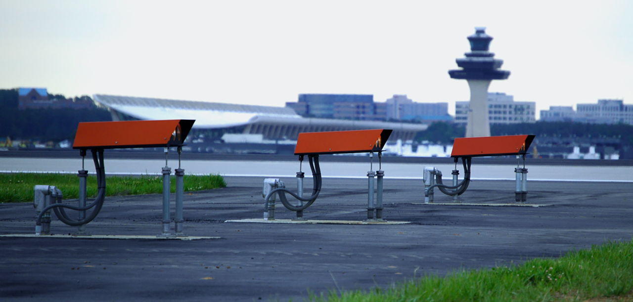
Siting, aiming and proving the approach path indicator — so the red and white signal a pilot sees marks the correct glide path.
AGL Visual Encyclopedia: PAPI commissioning
Common Commissioning Failures
This is where installation and commissioning connect directly with the AGL Troubleshooting Atlas. Tap a symptom to see possible causes.
Lights Operate but Photometry Fails
Possible Causes
- Optical contamination
- Incorrect alignment
- Incorrect fixture
- LED/lamp degradation
- Incorrect intensity
- Installation geometry problem
CCR Current Is Abnormal
Possible Causes
- Circuit fault
- Incorrect transformer
- Cable problem
- Excessive load
- Short circuit
One Fixture Remains Dark
Possible Causes
- Connector
- Transformer
- Fixture
- Cable
- Internal component
Multiple Fixtures Fail
Investigate Common Circuit Elements First
- CCR
- Feeder
- Cable
- Transformers
- Control
PAPI Indication Is Abnormal
Possible Causes
- Unit alignment
- Elevation
- Optical condition
- Electrical supply
- Geometry
Common Installation Defects
Frequent Root Causes
- Incorrect transformer rating
- Poor connector termination
- Damaged cable / poor earthing
- Incorrect elevation or PAPI alignment
- Wrong sign legend / poor sealing
Installation QA/QC — Three Levels & Hold Points
A strong installation QA/QC process should have three levels, preventing defects from being discovered only at final commissioning.
Incoming Inspection
Verify equipment before installation.
Installation Inspection
Verify the physical installation.
Commissioning Inspection
Verify electrical, functional and optical performance.
Recommended Installation Inspection Hold Points
Material approval
Foundation inspection
Cable installation
Transformer installation
Connector termination
Fixture installation
CCR/control connection
Pre-energization inspection
Electrical testing
First energization
Photometry/alignment
Final commissioning
Planned checks made at each stage of an AGL installation — base can, cable, connectors, fixture and earthing — so faults are found before the work is buried and the circuit is signed off before it is energised.
AGL Visual Encyclopedia: Installation quality checkpoints
Commissioning Package, Report & Punch-List Management
Commissioning Package Contents
- Approved drawings & equipment schedule
- Material & installation inspection records
- Cable, insulation & continuity test reports
- Transformer, CCR & earthing test records
- Functional & alignment records
- Photometry reports
- Punch-list & final commissioning report
- As-built drawings
Punch-List Entry Fields
- Defect number & location
- Affected equipment & description
- Severity — Critical/Major/Minor
- Corrective action & responsible party
- Target date & status
- Verification — re-test result
Re-Testing After Rectification
A defect is not closed simply because corrective work is completed: Defect → Rectification → Inspection → Re-test → Result → Close. A repaired cable repeats the electrical test; a replaced connector repeats continuity/insulation checks; a replaced fixture repeats functional and optical verification; an adjusted PAPI repeats alignment/photometry; a corrected CCR fault repeats operational testing.
The drawings and tables that show what was actually installed, circuit by circuit — checked against the site, kept current, and used for every later test and repair.
AGL Visual Encyclopedia: As-built records and circuit schedules
Airport Lighting Installation: Overview, Procedure & Method Statement
How an airfield lighting installation is planned, sequenced and documented before work starts on site.
Airport lighting installation
Airport lighting installation is the physical work of placing, connecting and securing airfield lighting equipment to the approved design. It covers civil preparation, cable and duct work, transformers, connectors, fixtures, CCR connection and earthing. Done well, it is the foundation for a commissioning that passes first time.
Airfield lighting installation overview
At overview level, installation follows a chain: engineering review, material receipt, civil and foundation verification, cable installation, transformer and connector installation, fixture installation and CCR connection. Each step has its own checks and hold points before the next one starts. See the AGL Installation Chain and Pre-Installation Engineering Review sections above.
AGL installation procedure
An AGL installation procedure sets out the order of work, who does it, the checks at each stage and the records to be kept. A typical procedure covers setting out, base and foundation work, cable laying, termination, fixture mounting, alignment and pre-energization inspection. It should follow the manufacturer's instructions and the project specification.
Airport lighting installation method statement
A method statement describes how a specific piece of airfield lighting work will be carried out safely and correctly. It normally covers scope, resources, sequence, equipment, quality checks, airside safety, permits, working-hours restrictions and coordination with airport operations. It is usually approved before work begins.
AGL method statement
An AGL method statement is the working document the site team follows. It should be specific to the system involved, such as edge lights, centreline lights or approach lights, and should state the hold points where inspection is required before work continues.
Elevated Lights, Base Cans, Shallow Bases & Foundation Details
Mounting arrangements and the civil work that supports the fixture.
Elevated light installation
Elevated light installation covers lights mounted above the surface on frangible supports, such as many edge and approach lights. Key points are correct height and orientation, frangible coupling arrangements, secure foundation, correct connector mating and protection of leads. Always check against the project drawings and the standard being followed.
Airfield lighting base can installation
Base can installation provides the housing in which an in-pavement fixture and its transformer sit. The base must be positioned and levelled to the design, drained and sealed as specified, and protected during paving and construction. Errors in position or level are difficult and costly to correct later.
AGL shallow base installation
Shallow base installation is used where depth is limited, for example in thin pavement or overlay situations. It needs the same attention to position, level, sealing and cable entry as a conventional base can, with extra care over fixture fit and drainage. Follow the manufacturer's instructions for the specific base type.
Airport lighting foundation details
Foundation details show how each fixture, base or support is anchored, including dimensions, materials and the cable and duct entry arrangements. They come from the civil and electrical drawings, and the installer should verify the foundation matches them before fitting equipment. See Civil & Foundation Verification above.
AGL Installation Testing, Defects & Pre-Commissioning
Proving the installation is sound before the circuit is energised.
AGL installation testing
Installation testing proves the work is electrically and mechanically sound before commissioning. It normally includes cable and insulation resistance testing, continuity checks, connector inspection and earthing checks, with results recorded against the project's acceptance criteria. Figures come from the project specification, so none are given here. See the Electrical Testing section above.
AGL installation defects
Typical installation defects include poorly made connectors, water ingress, damaged cable insulation, wrong fixture orientation, incorrect transformer rating, poor earthing and base level errors. Defects should be logged, assigned and closed with evidence, and repeat defects fed back into the method statement.
Airfield lighting pre-commissioning
Pre-commissioning is the set of checks done before first energization: verifying the installation matches drawings, completing insulation and continuity tests, confirming labelling and checking that protection and control settings are correct. It reduces the chance of a fault appearing during energization. See Pre-Energization Inspection above.
Airfield Lighting Commissioning: Procedure, SAT Testing, Report & Dossier
Bringing the system into service and documenting that it meets requirements.
Airfield lighting commissioning
Airfield lighting commissioning proves that the installed system works as designed and is ready for operational use. It covers energization, functional testing, brightness step checks, control and monitoring checks, alignment and photometric verification, followed by documented acceptance.
Airfield ground lighting commissioning
Airfield ground lighting commissioning is commissioning of the full AGL system, including circuits, CCRs, fixtures and control. It is carried out system by system, such as runway, taxiway and approach lighting, and ends with a commissioning package and handover. See Commissioning by System above.
AGL commissioning procedure
An AGL commissioning procedure defines the order of tests, the conditions for each, acceptance criteria, safety rules and the people who witness or sign off. It is normally agreed with the airport operator before testing begins.
Airport lighting SAT testing
SAT, or site acceptance testing, is the formal demonstration on site that the installed system meets the contract and design requirements. It is witnessed by the client or their representative, and results are recorded and signed off. Test content and acceptance values come from the project specification.
Airfield lighting commissioning report
The commissioning report records what was tested, the results, any deviations and their closure, and the final status of the system. It should be traceable to circuits, equipment and test records, and signed by the responsible parties. See Commissioning Package, Report & Punch-List Management above.
AGL commissioning report template
A commissioning report template gives each project a consistent layout: project and system identification, equipment list, test results, punch list, deviations, photographs and sign-off blocks. Adapt the template to your project specification and the client's required format.
AGL commissioning dossier
The commissioning dossier is the complete handover file. It typically gathers as-built drawings, test records, calibration certificates, commissioning reports, punch-list closure, manuals and warranties, so the operator has a full record of the system as delivered.
The planned order for bringing an AGL system into service — each stage passed and recorded before the next begins.
AGL Visual Encyclopedia: The commissioning sequence Final acceptance
AGL Installation & Commissioning Checklist
A complete project should be checked across four stages. Tick items off as you review a project — this resets on reload.
Pre-Installation
Installation
Testing & Energization
Handover
Installation vs Commissioning
| Installation | Commissioning |
|---|---|
| Physical work | Verification work |
| Equipment placement | Equipment performance |
| Cable installation | Cable testing |
| Transformer installation | Transformer verification |
| Fixture installation | Optical verification |
| CCR connection | CCR functional testing |
| Connector termination | Electrical testing |
| Mechanical assembly | Alignment |
| Construction | Acceptance |
Standards & References
Installation and commissioning should be performed against the current applicable edition of the relevant standards, project specifications and manufacturer instructions. Exact acceptance criteria should always be taken from the applicable standard, approved design and project specification — never one universal value applied to every installation.
Quick Knowledge Check
Q1. What is the basic principle of AGL commissioning philosophy?
Q2. A defect is closed once corrective work is completed. True or false?
Q3. Lights turn ON during first energization. Is the system commissioned?
AGL Installation & Commissioning Knowledge Hub
Transformer Installation
Understand isolation transformer installation and testing.
Browse components →CCR Installation & Testing
Study CCR installation, connection and functional testing.
Open Design & Electrical Engineering →Explore the AGL Engineering Knowledge Hub
Fundamentals
Standards & Compliance
Runway, Taxiway & Approach Lighting
Surface Movement & Safety
PAPI
Electrical Engineering & Power
Photometry & Testing
Maintenance, Inspection & Safety
Resources, Documentation & Careers
Frequently Asked Questions
Q1What is AGL installation and commissioning?
AGL installation is the physical installation and connection of airfield lighting equipment according to approved drawings, specifications and applicable standards. AGL commissioning is the systematic process of testing, measuring, adjusting and verifying the installed system before it is accepted for operational use. Commissioning verifies the complete system, not simply whether the lights turn on.
Q2Why does installation quality matter so much in AGL?
An installation error can create a system-level problem. For example, an incorrect transformer rating can cause abnormal fixture operation, a poor connector installation can cause intermittent light failure, incorrect cable termination can lead to insulation failure, incorrect fixture elevation can cause an optical performance problem, and water ingress can cause repeated electrical failures.
Q3What is the AGL installation and commissioning philosophy?
Do not energize first and inspect later. The installation should progress through controlled stages, never in reverse: verify, install, inspect, test, energize, measure, adjust, verify again, document and hand over.
Q4What are the stages from design to handover?
The process runs through design, installation, inspection, electrical testing, functional testing, alignment, photometry, commissioning and handover.
Q5What should be checked before AGL installation starts?
A pre-installation review covers drawings (approved layout, circuit drawings, cable routing, equipment locations, foundation drawings), equipment (correct items, quantities, ratings, specifications and manufacturer documentation) and the site (work area released, survey references, civil works completed, cable routes, foundations, access and work permits).
Q6Why is equipment traceability important?
Every major AGL component should be inspected on receipt and traceable afterwards. A traceability record can include equipment ID, manufacturer, model, serial number, rating, circuit number, location, installation date and test reference. It is particularly important for CCRs, isolation transformers, light fixtures, PAPI units, signs and control equipment.
Q7Why must civil and foundation work be verified first?
Foundation location, dimensions, elevation, orientation, anchors, drainage, cable entry, mounting interface and frangibility requirements must be verified before equipment is installed. Incorrect civil work should never be compensated for with uncontrolled equipment adjustments.
Q8How can cable damage be avoided during installation?
Avoid excessive pulling force, sharp bends, crushing and abrasion, damaged insulation, improper storage, uncontrolled cable loops and incorrect termination. Cable damage may not be visible externally, so electrical testing is essential, and unnecessary joints should be avoided in critical series circuits.
Q9What is verified when installing the series circuit and isolation transformers?
Verify the circuit sequence, transformer connection, cable continuity, connector compatibility, circuit identification, circuit separation and correct termination. Before installing a transformer, also check its rating, primary and secondary connectors, physical condition, identification, insulation condition, location, water protection and cable compatibility.
Q10How should light fixtures and connectors be installed?
Fixture installation should follow the approved layout strictly, never assumed positions, with correct type, location, orientation, elevation, frangibility arrangement, transformer connection and optical direction. A connector should never be assumed correctly installed simply because it fits, since a poor connector can cause high-resistance connections, intermittent faults or complete circuit failure.
Q11How to commission an AGL system?
Commissioning an AGL system follows a set order: complete installation and pre-commissioning checks, run insulation and continuity tests, carry out a pre-energization inspection, energize each circuit under controlled conditions, then do functional testing at each brightness step. Next check control and monitoring, alignment and photometry, and close out the punch list. The results go into the commissioning report and dossier, and acceptance values come from your project specification.
Engineering & Expert Notes
Check Before You Cover
Hold PointsDefine hold points for work that will be buried or concealed. Verification afterwards is expensive and sometimes impossible.
Inspect Materials on Receipt
ReceiptCheck type, rating, markings and condition against the approved submittal when equipment arrives, and quarantine anything that does not match.
Verify Civil Work Before the Electrical Work Depends on It
FoundationsLevels, positions and drainage set by civil teams determine installation quality. Confirm them against the drawings before fixtures are fitted.
Test in Stages, Not Only at the End
TestingCable, transformer and circuit tests at each stage isolate problems when they are cheap to fix. Record results as you go.
Electrical Pass Does Not Mean Photometric Pass
VerificationA circuit can be healthy electrically while optical output or alignment is wrong. Include optical verification in the commissioning scope.
Build the Handover File as the Work Proceeds
HandoverCollecting records at the end invites gaps. Compile test sheets, as-builts and certificates progressively and review them before completion.
Understand AGL. Build Your Engineering Skills.
You now understand how AGL systems are installed and commissioned on site — from cable laying and terminations to testing, snagging and final handover.
Take the next step with Precision AGL Academy.
Learn AGL Step by Step
Build your knowledge through structured technical learning covering:
Move from understanding how AGL works to developing the practical knowledge needed to analyse, operate and maintain complete AGL systems.
Follow the Academy
Important Notice, Disclaimer & Limitation of Liability
Please read before relying on any content on this page or on any record downloaded from it.
- Purpose and intended users. This page is an independent educational and informational reference for competent, suitably trained and authorised airfield ground lighting (AGL) and aerodrome personnel. It is not professional engineering, legal or regulatory advice, and using it creates no professional or client relationship. Learning-path and Academy references describe stages of learning only and are not a certification, accreditation or authorisation.
- Safety. Work on series circuits, constant current regulators (CCRs), isolating transformers, cables, connectors and lighting fixtures can be fatal. Always apply the aerodrome’s permit-to-work and isolation/LOTO procedures, prove dead, use correctly rated instruments and PPE, and follow the manufacturer’s instructions. Nothing here authorises work on live equipment or the bypassing of any safety device or interlock.
- Aviation operations. Nothing on this page authorises return to service, the installation, adjustment or modification of any aviation visual aid, a change of operating category (CAT I/II/III), a NOTAM or any aerodrome certification decision. These rest with the aerodrome operator, the air navigation service provider and the competent regulator.
- Standards, regulations and named sources. References to ICAO, FAA, EASA, DGCA, AAI, IEC, IEEE, ISO, BIS and other standards, regulations, AIP material and published sources, and statements about what a named airport, State or authority has published, are summaries for orientation as understood when the page was prepared. They are not official text, may be incomplete, amended or superseded, and have not been independently verified. Consult the current official editions, including the current AIP, AIRAC cycle and NOTAMs. Following this content does not guarantee compliance with any law, standard or approval, and official documents, regulations, the approved design and manufacturers’ instructions always prevail.
- Generic content; no warranty. Values, tolerances, intervals, sequences, examples, checklists and pass/fail or “compliant” wording are generic and indicative; real installations differ in design, make, model, age and condition. Content is provided “as is” and “as available”, without warranty of any kind, express or implied, including accuracy, completeness, currency or fitness for a particular purpose.
- Enquiries and services. The email and call buttons on this page open your own email or telephone application; nothing is sent to us until you send it. Descriptions of consultancy, support, documentation or other services are not an offer, quotation or tender, and contacting us or our replying creates no engagement, duty of care or contract; an engagement exists only under a written agreement. We are not a regulator or certification body, and “support” does not mean certification or approval. Please do not send confidential, classified or security-sensitive information.
- Images, diagrams and credits. Photographs on this page carry a credit line in their caption naming the source and, where stated, the licence (for example U.S. Government public-domain works or openly licensed images). They illustrate a type of equipment or situation, may not show the exact item described, imply no endorsement by or affiliation with any person, organisation or manufacturer shown, and remain subject to their owners’ rights. Diagrams are original schematic illustrations, are not to scale and are not engineering drawings. To request a correction, credit or removal, write to the contact address below.
- Limitation of liability. To the fullest extent permitted by applicable law, Precision AGL Academy and its owners, authors and contributors are not liable for any injury, death, loss, damage, downtime, penalty or regulatory consequence, whether direct or indirect, arising from the use of, reliance on, or inability to use this content. Nothing in this notice excludes or limits any liability that cannot lawfully be excluded or limited.
- Independence and trademarks. This is an independent publication, not affiliated with or endorsed by ICAO, the FAA, EASA, the IEC, DGCA, AAI, any airport, regulator, employer or equipment manufacturer. Third-party names, standard designations and trademarks (including Megger®) belong to their respective owners and are used for identification only.
- Copyright and use. © 2026 Precision AGL Academy. All rights reserved. The text, structure, diagrams and compilation of this page are protected by copyright. You may read it and use it for personal reference and internal training, keeping this notice attached; any other copying, republication, scraping or commercial use needs our prior written permission. Credited third-party photographs remain subject to their owners’ terms.
- Corrections. Content is reviewed periodically, with no obligation to update. To report an error, safety concern, copyright, privacy or other rights issue, write to precisionaglsolutions@gmail.com.