How Does PAPI Work?
Why PAPI uses white and red lights, what 2 white and 2 red means, and the optical engineering behind the four-light indication: approach slope, threshold crossing height, aiming, photometry and maintenance.
How Does PAPI Work?
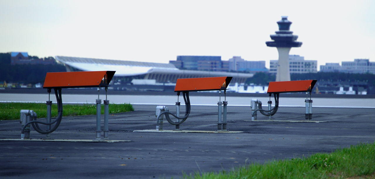
A Precision Approach Path Indicator (PAPI) gives pilots visual information about the aircraft's position relative to the desired approach slope. A conventional PAPI is four light units in a horizontal row beside the runway. Each unit produces a precisely controlled transition between white and red light, and as the aircraft moves above or below the designed path, the combination of white and red changes.
Think of it as four light units + four optical settings + one approach reference. For the pilot it is simple. For the engineer, the units need the correct location, elevation, spacing, horizontal alignment, vertical aiming and optical performance for the indication to represent the intended path.
| Indication | Meaning |
|---|---|
| 4 White | Aircraft significantly above the indicated approach path |
| 3 White + 1 Red | Slightly above the indicated approach path |
| 2 White + 2 Red | Approximately on the indicated approach path |
| 1 White + 3 Red | Slightly below the indicated approach path |
| 4 Red | Significantly below the indicated approach path |
The Precision Approach Path Indicator: four light units beside the runway that show the pilot, by colour alone, whether the aircraft is on, above or below the approach slope.
AGL Visual Encyclopedia: A PAPI PAPI unit arrangement
PAPI Indication Simulator
Move the slider to change the aircraft's angle above the horizontal. A unit shows white when the aircraft is above its aiming angle and red when below.
Why Red and White? The Optical Transition
Why does PAPI show red and white?
Each unit is designed so that, viewed from the approach, one angular region appears white, another appears red, and the change between them happens at a controlled elevation angle. What matters is not that a unit can make two colours, but that the transition sits at a defined vertical viewing angle. The four units are then aimed at progressively different elevations, which turns a continuous change in aircraft height into an intuitive pattern of colours.
Side view (angles exaggerated): the aircraft crosses each unit's transition line as it moves up or down
Does every unit point at the same angle?
No. The four units have different vertical aiming settings, carefully related so the transitions occur at the required angular positions. Installation is therefore not "install four units in a row" but survey, elevation, spacing, alignment, individual aiming and optical verification.
Why one moved unit matters
If Unit 3 moves, it may still turn on and show white and red, yet its transition now happens at the wrong elevation, changing the indication an approaching aircraft sees. PAPI aiming is a safety-related engineering parameter, not just a mechanical adjustment.
What PAPI Does and Does Not Tell the Pilot
Angular reference
PAPI shows the angular relationship between the aircraft line of sight and the four beams. 2 White + 2 Red means approximately on the indicated path.
Not an altimeter
It does not give altitude, airspeed, distance or attitude. The same indication occurs at different altitudes depending on distance from the runway.
Colour logic
White and red are used for vertical approach-path indication only. Runway and taxiway lighting use a wider colour set for their own functions.
The descent slope the PAPI marks for the pilot. Two red and two white means on the path; more white means high, more red means low.
AGL Visual Encyclopedia: The PAPI glide path PAPI beam
Approach Slope, TCH and MEHT
Threshold Crossing Height (TCH) relates the visual approach path to aircraft height over the threshold. Minimum Eye Height over Threshold (MEHT) is the associated eye-height characteristic of the approved PAPI and runway geometry. Both belong to the larger approach geometry, so a PAPI cannot be designed by just choosing a four-light unit.
Is PAPI always 3°?
No. 3.00° is common, but the correct value is the one set by the approved runway design and current aeronautical information. Indian AAI eAIP entries publish the PAPI side, approach angle and MEHT per runway direction, with examples at 3.00° and at 3.25°. Check the current eAIP for any runway.
Why location matters
Location depends on threshold position, runway elevation, approach slope, TCH/MEHT, obstacles, aircraft considerations and runway geometry. Moving a PAPI without recalculating changes its relationship to the intended path. Resurfacing, extension, re-thresholding or threshold relocation should trigger a PAPI engineering review.
The vertical angle at which each PAPI unit’s beam changes from white to red. Four units, four angles, spread around the approach slope.
AGL Visual Encyclopedia: The PAPI elevation angle
PAPI vs APAPI, ILS and Approach Lighting
| System | What it is | Relationship to PAPI |
|---|---|---|
| APAPI | Abbreviated configuration using fewer units, giving a different indication arrangement | Choice depends on aerodrome design and operational requirements |
| ILS | Radio-navigation precision approach system | Different system. They can be used together, and PAPI gives an independent visual reference. PAPI does not replace ILS |
| Approach lighting | Visual reference extending before the threshold | Different information; both work together in the visual approach environment |
| Runway lighting | Edge, threshold, end and centreline lights | The pilot sees the whole visual environment, not PAPI in isolation |
Four units against two. The same white-above, red-below code, but the PAPI shows the error in finer steps.
AGL Visual Encyclopedia: PAPI versus APAPI: what is the difference VASI versus PAPI ILS glide slope

PAPI Photometry: Why "ON" Is Not Enough
Visual inspection tells you a unit is on. Photometry tells you how much light it produces and where it goes. A PAPI can be electrically functional but photometrically defective because of a dirty lens, optical deterioration, incorrect aiming, a damaged optical component, an LED/driver problem or mechanical displacement.
Intensity
A low result can come from contamination, optical degradation, electrical problems, LED/driver degradation or wrong test geometry. Verify the measurement before replacing equipment.
Colour and chromaticity
Colour depends on optical components, filters, lens condition, LED performance, contamination and correct replacements. AAI field-photometry specifications include colour and chromaticity for AGL and PAPI testing.
Beam alignment
Aiming errors come from foundation movement, impact, loose hardware, construction, incorrect adjustment or mechanical degradation, so verify aiming periodically.
Review design data
Runway, PAPI location, approach angle, unit arrangement, criteria.
Inspect units
Lenses, housings, foundations, surroundings.
Verify alignment
Horizontal and vertical settings.
Energize
Operate under the defined test condition.
Measure
Record the relevant photometric parameters.
Evaluate
Compare against the applicable criteria.
Correct
Clean, align, repair or replace.
Retest
Confirm the result.
Related Guides
AGL photometry Visual inspection vs photometric testing Photometric test data analyzerMaking sure each of the four units still shows its white-to-red change at the right angle and points parallel to the runway, and re-setting it when it has moved.
AGL Visual Encyclopedia: A PAPI re-aligned
Electrical Chain and Isolating Transformers
The isolating transformer that feeds each PAPI unit — one per unit, its primary in the series circuit, placed in the base can, the unit or a nearby pit, and joined to the lamps by a short secondary lead.
AGL Visual Encyclopedia: A PAPI transformer arranged PAPI power supply
PAPI Maintenance and Testing After Work
| Category | Check |
|---|---|
| Optical | Lens, colour, intensity, beam coverage, beam alignment |
| Mechanical | Foundation, mounting, horizontal alignment, vertical aiming, unit relationship |
| Electrical | Supply, cable, connector, transformer, insulation, earthing |
| Functional | All units on, colour indication, control, brightness, final indication |
| Final | Retest and documentation |
After maintenance follow this order: alignment check → electrical check → photometry → functional test → retest → documentation, so there is evidence that the work restored intended performance. AAI maintenance specifications give examples of this integrated approach, including physical inspection, lens cleaning, PAPI angle checks, calibration, earthing, insulation and transformer and connector checks.
Flight inspection
Ground maintenance and photometry are not formal airborne verification. Where the approved procedure requires it, PAPI is evaluated from the air. An AAI document describes ground calibration before flight calibration, with checks such as PAPI setting angles, brilliancy control and compatibility with the ILS glide path. The current airport and authority procedure decides when it is required.
Related Guides
AGL maintenance India PAPI/APAPI maintenance PAPI Alignment, Testing & Maintenance Field GuideFive checks that prove each unit is sound, set at the right angle, aimed down the runway and changing colour exactly where it should.
AGL Visual Encyclopedia: A PAPI tested PAPI inspection
PAPI in India
PAPI is widely deployed across Indian aerodromes. AAI eAIP material gives runway-specific data (PAPI side, approach angle and MEHT), so installed values differ between aerodromes and runway directions. For Indian projects the basis should include current DGCA requirements, AAI or project specifications, approved aerodrome information and manufacturer requirements, and the work chain runs survey, design review, civil foundation, installation, electrical integration, aiming, photometry, testing, commissioning and maintenance.
PAPI and ICAO
ICAO Annex 14 Volume I is the principal international aerodrome standard framework, and ICAO's Aerodrome Design Manual Part 4 (Visual Aids) gives engineering guidance on visual approach slope indicators. The ICAO Store lists Annex 14 Vol. I as the 9th Edition (July 2022) as amended, including Amendment 18. Corrigenda have followed, so confirm the latest corrigendum or edition and your State's implementation before relying on any requirement.
How the four units of a wing bar stand beside the runway: one straight line, equally spaced, in a fixed order, so the pilot reads them as a single bar of lights.
AGL Visual Encyclopedia: The PAPI unit arrangement
Common PAPI Problems
Click a fault to see where to investigate.
All units off
Investigate
- Agl circuit
- Ccr
- Transformer circuit
- Control
- Power
One unit off
Investigate
- Transformer
- Connector
- Secondary cable
- Internal unit
One unit dim
Investigate
- Lens
- Optical system
- Led/driver
- Electrical supply
- Transformer
Wrong colour pattern
Investigate
- Aiming
- Optical condition
- Colour performance
- Unit-to-unit relationship
PAPI misaligned
Investigate
- Foundation
- Mounting
- Horizontal alignment
- Vertical aiming
Photometry failure
Investigate
- Measurement setup
- Operating condition
- Optical condition
- Electrical condition
- Aiming
The symptom shows whether a unit, the circuit, the aim or the optics failed, and a short set of visual, electrical and inclinometer checks confirms it.
AGL Visual Encyclopedia: How do you troubleshoot a PAPI
Digital Integration and LED PAPI
Monitoring
Depending on the installation, PAPI can interface with AGL control, ALCMS, remote monitoring, maintenance systems and operational procedures, so status is monitored as part of the airfield system.
LED PAPI
Opportunities include lower energy use, longer component life, fewer lamp replacements and better diagnostics. Weigh these together with optical performance, reliability, maintainability and operational requirement.
The PAPI reports its state over a link to the control room, so a failed unit is found at once. The reading is a warning; the signal itself is still proved on site.
AGL Visual Encyclopedia: A PAPI monitored remotely Smart PAPI ALCMS to PAPI
Quick Knowledge Check
Q1. What does 2 White + 2 Red mean?
Q2. Why does moving one PAPI unit change the indication?
Q3. Is every PAPI set to exactly 3°?
Q4. Can a PAPI be switched on but still defective?
Q5. What does PAPI give the pilot?
Explore More AGL Engineering
PAPI Engineering Guide
Siting, geometry, foundations and electrical systems.
Open PAPI Engineering Guide →PAPI Installation & Aiming Handbook
Installation procedure and aiming angles.
Open PAPI Installation & Aiming Handbook →PAPI Alignment, Testing & Maintenance
Aiming records, checks and maintenance.
Open PAPI Alignment, Testing & Maintenance →AGL Photometric Testing Procedure
Field photometry, rectification and retesting.
Open AGL Photometric Testing Procedure →Runway Lighting Photometry
Intensity, coverage, colour and testing.
Open Runway Lighting Photometry →Testing & Commissioning
Electrical, optical and handover testing.
Open Testing & Commissioning →Simple for the Pilot. Precise for the Engineer.
Go from the basics of PAPI to engineering, installation, photometry and maintenance in the AGL knowledge base.
Explore the AGL Engineering Knowledge Hub
Fundamentals
Standards & Compliance
Runway, Taxiway & Approach Lighting
Surface Movement & Safety
PAPI
Electrical Engineering & Power
Photometry & Testing
Maintenance, Inspection & Safety
Resources, Documentation & Careers
How PAPI Works: FAQ
Q1How does PAPI work?
PAPI uses four optical units with different vertical aiming settings. Each has a controlled white/red transition, and the combination the pilot sees shows whether the aircraft is above, approximately on, or below the intended approach path.
Q2What does PAPI stand for?
Precision Approach Path Indicator.
Q3How many lights are in a PAPI?
A conventional PAPI uses four light units.
Q4Why does PAPI use red and white?
The two colours give a simple visual indication of the aircraft's relationship to the intended approach slope.
Q5What does 2 white and 2 red mean?
The aircraft is approximately on the intended PAPI approach path.
Q6What does 3 white and 1 red mean?
The aircraft is slightly above the indicated approach path.
Q7What does 1 white and 3 red mean?
The aircraft is slightly below the indicated approach path.
Q8What does 4 red mean on PAPI?
The aircraft is significantly below the indicated visual approach path.
Q9Does 4 white always mean the same altitude?
No. PAPI gives an angular visual reference, not a fixed altitude. Actual altitude depends on distance and position relative to the runway.
Q10Is every PAPI set to 3 degrees?
No. 3.00° is common, but designs can differ. Indian AAI publications show examples at both 3.00° and 3.25°.
Q11What is PAPI TCH?
Threshold Crossing Height: the relationship between the approach path and aircraft height over the threshold.
Q12What is PAPI MEHT?
Minimum Eye Height over Threshold, associated with the approved PAPI and runway approach geometry and published per runway direction in Indian AAI aeronautical information.
Q13Is PAPI the same as ILS?
No. PAPI is a visual approach-slope indicator and ILS is a radio-navigation system. They can be used together.
Q14Is PAPI the same as approach lighting?
No. They provide different visual information and work together in the approach environment.
Q15Does PAPI need photometric testing?
It may, during commissioning, inspection, maintenance or acceptance per the applicable programme. Measurements can include intensity, colour, chromaticity and beam characteristics.
Q16Can PAPI work without ILS?
Yes. It can give visual approach-slope guidance on appropriately equipped runways, subject to the applicable design and operational requirements.
Q17Can PAPI be on but still defective?
Yes. It can operate electrically while having incorrect aiming, low intensity, damaged optics or poor colour.
Q18Why is PAPI aiming important?
The white/red transition is angular, so changing a unit's physical aiming changes where the transition is seen.
Q19What happens if one PAPI unit moves?
Its transition moves relative to the other three units, potentially changing the indication presented to the pilot.
Q20Does PAPI need maintenance?
Yes. Maintenance should cover optical, mechanical, electrical, aiming, photometric and functional performance.
Engineering & Expert Notes
Indications Depend on the Pilot's Position
PrincipleThe red and white pattern changes with the angle of approach relative to the set slope.
Setting Angles and Siting Work Together
GeometryCorrect angles are only part of the story. Position relative to the threshold is equally important.
A Light That Is On May Still Be Wrong
PhotometryCheck intensity, colour and the sharpness of the transition, not just illumination.
PAPI Does Not Replace Other Aids
LimitsIt provides visual slope guidance, and pilots use it together with other information.
Re-Check After Impacts and Civil Works
MaintenanceMovement of units or changes in surroundings can alter the indications.
Keep the Calibration Record
RecordsDocument angles and measurements so changes can be recognised.
Understand AGL. Build Your Engineering Skills.
You now understand how PAPI provides visual approach slope guidance — from unit arrangement and angular settings to siting, commissioning and troubleshooting.
Take the next step with Precision AGL Academy.
Learn AGL Step by Step
Build your knowledge through structured technical learning covering:
Move from understanding how AGL works to developing the practical knowledge needed to analyse, operate and maintain complete AGL systems.
Follow the Academy
Important Notice, Disclaimer & Limitation of Liability
Please read before relying on any content on this page or on any record downloaded from it.
- Purpose and intended users. This page is an independent educational and informational reference for competent, suitably trained and authorised airfield ground lighting (AGL) and aerodrome personnel. It is not professional engineering, legal or regulatory advice, and using it creates no professional or client relationship. Learning-path and Academy references describe stages of learning only and are not a certification, accreditation or authorisation.
- Safety. Work on series circuits, constant current regulators (CCRs), isolating transformers, cables, connectors and lighting fixtures can be fatal. Always apply the aerodrome’s permit-to-work and isolation/LOTO procedures, prove dead, use correctly rated instruments and PPE, and follow the manufacturer’s instructions. Nothing here authorises work on live equipment or the bypassing of any safety device or interlock.
- Aviation operations. Nothing on this page authorises return to service, the installation, adjustment or modification of any aviation visual aid, a change of operating category (CAT I/II/III), a NOTAM or any aerodrome certification decision. These rest with the aerodrome operator, the air navigation service provider and the competent regulator.
- Standards, regulations and named sources. References to ICAO, FAA, EASA, DGCA, AAI, IEC, IEEE, ISO, BIS and other standards, regulations, AIP material and published sources, and statements about what a named airport, State or authority has published, are summaries for orientation as understood when the page was prepared. They are not official text, may be incomplete, amended or superseded, and have not been independently verified. Consult the current official editions, including the current AIP, AIRAC cycle and NOTAMs. Following this content does not guarantee compliance with any law, standard or approval, and official documents, regulations, the approved design and manufacturers’ instructions always prevail.
- Generic content; no warranty. Values, tolerances, intervals, sequences, examples, checklists and pass/fail or “compliant” wording are generic and indicative; real installations differ in design, make, model, age and condition. Content is provided “as is” and “as available”, without warranty of any kind, express or implied, including accuracy, completeness, currency or fitness for a particular purpose.
- Calculators and interactive tools. Sliders, calculators, selectors and animated demonstrations on this page are teaching illustrations. Their starting values are examples, they give approximate results from simplified models, and they must not be used to design, size, set, test, accept or operate real equipment, or to support a financial or procurement decision. Values you enter are processed in your browser and are not sent to us.
- Images, diagrams and credits. Photographs on this page carry a credit line in their caption naming the source and, where stated, the licence (for example U.S. Government public-domain works or openly licensed images). They illustrate a type of equipment or situation, may not show the exact item described, imply no endorsement by or affiliation with any person, organisation or manufacturer shown, and remain subject to their owners’ rights. Diagrams are original schematic illustrations, are not to scale and are not engineering drawings. To request a correction, credit or removal, write to the contact address below.
- Limitation of liability. To the fullest extent permitted by applicable law, Precision AGL Academy and its owners, authors and contributors are not liable for any injury, death, loss, damage, downtime, penalty or regulatory consequence, whether direct or indirect, arising from the use of, reliance on, or inability to use this content. Nothing in this notice excludes or limits any liability that cannot lawfully be excluded or limited.
- Independence and trademarks. This is an independent publication, not affiliated with or endorsed by ICAO, the FAA, EASA, the IEC, DGCA, AAI, any airport, regulator, employer or equipment manufacturer. Third-party names, standard designations and trademarks (including Megger®) belong to their respective owners and are used for identification only.
- Copyright and use. © 2026 Precision AGL Academy. All rights reserved. The text, structure, diagrams and compilation of this page are protected by copyright. You may read it and use it for personal reference and internal training, keeping this notice attached; any other copying, republication, scraping or commercial use needs our prior written permission. Credited third-party photographs remain subject to their owners’ terms.
- Corrections. Content is reviewed periodically, with no obligation to update. To report an error, safety concern, copyright, privacy or other rights issue, write to precisionaglsolutions@gmail.com.