Airfield Ground Lighting Components Complete AGL Component Guide
The electrical, optical, mechanical and control components of an AGL system, how they connect, and how to select, test, maintain and troubleshoot them as one chain. Each category links to a detailed engineering guide.
What Are AGL Components?
An Airfield Ground Lighting (AGL) system is built from interconnected electrical, optical, mechanical and control components. Each has a specific function, and the performance of one can directly affect the others. Understanding them supports design, selection, procurement, installation, testing, commissioning, photometric verification, maintenance, troubleshooting and rehabilitation.
Electrical
Supply, distribute, regulate and connect electrical power.
Lighting
Produce the required visual guidance.
Mechanical
Mount, protect, position and support the lighting equipment.
Control
Operate, monitor and manage the lighting system.
AGL System Architecture
Power path
Airport power supply feeds the CCR, which drives the primary circuit. Each light on the circuit is fed through its own isolation transformer.
Control path
ATC and airport operations command the ALCMS, which controls the CCRs and receives monitoring information. The CCRs feed the AGL series circuits and airport light fixtures.
Five relationships that must all work
| Path | Chain |
|---|---|
| Electrical | CCR → cable → transformer → connector → fixture |
| Mechanical | Foundation → base → mounting → fixture |
| Optical | Light source → optics → lens → beam |
| Control | Operator → ALCMS → CCR → circuit → fixture |
| Monitoring | Fixture, circuit or CCR → monitoring → ALCMS → operator |
Follow a Component Path
Pick a path to see what to check along it. This is a learning aid; the project specification sets the actual tests.
Check along the path
Watch for
Electrical AGL Components
Constant Current Regulator (CCR)
Maintains the selected current through the series lighting circuit. May also provide multiple intensity steps, local and remote control, monitoring, fault indication, protection and an ALCMS interface, so it is both a power and, in monitored systems, a control component. CCR working principle
Isolating transformer
Connects an individual light to the series circuit while separating primary and secondary. Match primary and secondary current, wattage, frequency, insulation, environmental protection, connectors and fixture compatibility. Airport isolating transformer
Primary cable
Carries the controlled series current. Select for voltage rating, insulation, conductor size, environment, circuit length, temperature, mechanical protection and the airport specification. A primary fault can affect multiple fixtures. Cables and connectors
Secondary cable
Links the transformer secondary to the fixture, generally for one fixture. Common problems: connector failure, cable damage, insulation deterioration, water ingress, mechanical damage and high-resistance connections.
Connectors
Join primary cable to transformer, transformer to secondary lead, and secondary lead to fixture. Primary connectors serve the series circuit; secondary connectors serve the transformer-to-fixture link. A mated connector can still have poor contact or moisture.
Junction boxes
Protected space for connections, and for transformers in some designs. Select for installation environment and loading. Junction boxes and housings
Lighting Components
Each light type has its own optical characteristics, installation geometry, colour requirements, beam pattern, photometric criteria and maintenance needs.
| Component | Function | Notes |
|---|---|---|
| Runway edge lights | Lateral runway guidance | |
| Threshold lights | Identify the runway threshold | |
| Runway end lights | Visual indication at the runway end | |
| Runway centreline lights | Longitudinal guidance where installed | |
| Touchdown zone lights | Guidance within the touchdown area | |
| Approach lights | Approach visual guidance | A coordinated system: units, centreline and crossbar lights, elevated and inset fixtures, sequencing, power, PAPI |
| Taxiway edge lights | Define taxiway lateral limits | |
| Taxiway centreline lights | Centreline guidance | |
| Stop bars | Holding-point information | |
| Runway guard lights | Awareness at runway holding positions | Elevated or in-pavement; may flash; may integrate with runway protection logic |
| PAPI | Visual approach-slope guidance | Four units; 4 white to 4 red as the aircraft descends |
| APAPI | Abbreviated PAPI, generally two units | A separate configuration, not just a smaller PAPI |
| REIL | Distinctive runway end or threshold identification | Typically two units, control, power, synchronization where applicable |
PAPI needs particular attention
Siting, elevation, spacing, horizontal alignment, aiming, threshold crossing geometry, photometry and maintenance. Authority requirements and the airport design decide between PAPI and APAPI.
Taxiway lighting works with
Taxiway signs, centreline guidance, stop bars, control systems and monitoring.
Related Guides
Runway lighting systems Taxiway lighting systems Approach lighting systems PAPI engineering guide PAPI installation and aiming ICAO PAPI requirements Runway guard lights and stop bars Taxiway guidance signs LED AGL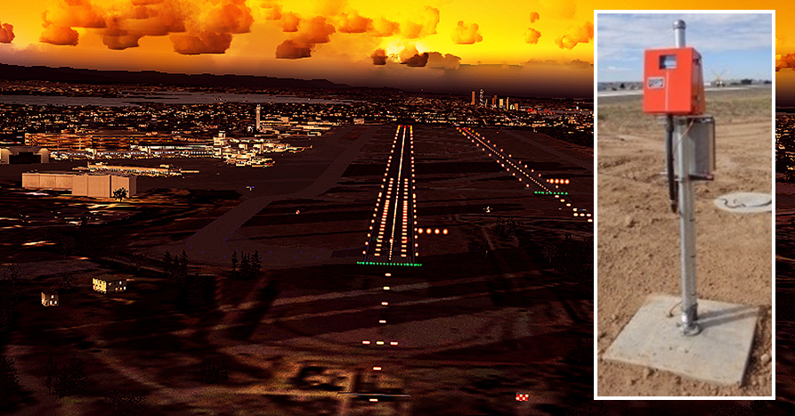
Mechanical AGL Components
Mechanical infrastructure keeps equipment positioned and protected. It influences fixture elevation, alignment, stability, drainage, maintenance access, vehicle and aircraft loading, and frangibility where applicable.
Light bases
The mounting interface between airfield infrastructure and the fixture; depending on design, also a transformer housing, junction box or cable-access enclosure. Consider loading, diameter, depth, material, corrosion protection, drainage, fixture interface, cable entry and alignment.
Transformer housings
Physical protection for an isolation transformer. Consider transformer size, depth, drainage, cable routing, connector access, mechanical protection and environment. Select housing and transformer as a compatible system.
Frangible supports
Designed to break away under applicable conditions rather than become an unacceptable obstacle hazard. Used with elevated runway, taxiway and approach lights, signs and PAPI. Consider fixture weight, mounting height, support arrangement, break point, foundation and nearby aircraft movement.
Mounting assemblies
Mounting plates, baseplates, bolts, spacer rings, extensions, adjustment mechanisms, brackets, frangible couplings and elevation adjustment components. Incorrect mounting causes misalignment, wrong elevation, instability and poor photometric performance.
Control and Monitoring Components
Modern AGL systems increasingly use centralized control and monitoring: ALCMS, CCR control interfaces, remote-control panels, monitoring equipment, circuit selectors, PLC and RTU interfaces, communication equipment, status panels and alarms.
ALCMS
Centralized control and monitoring of lighting circuits: circuit on/off, intensity selection, status monitoring, fault alarms, event logging, equipment status, remote control and interfaces with airport operational systems. It is part of the control and monitoring architecture, not only a user interface.
CCR control
The interface between the control system and the regulator: start and stop, brightness selection, local or remote selection, status, fault indication and monitoring. Commissioning should verify both the command and the feedback.
Remote control
Lets authorized staff operate lighting without being at the CCR cabinet: on/off, intensity step, status and alarms. May sit in ALCMS, a control desk, SCADA or an airport operations control system.
Monitoring
Covers CCR status, circuit status, lighting failures, alarms, communication status, control-system faults and equipment availability, so staff can respond to failures sooner.

AGL Components by Function
| Function | Main components |
|---|---|
| Power regulation | CCR |
| Primary distribution | Primary AGL cable |
| Electrical isolation | Isolation transformer |
| Secondary connection | Secondary cable and connector |
| Visual guidance | Runway, taxiway and approach lights |
| Approach guidance | PAPI and APAPI |
| Runway identification | REIL |
| Runway protection | Runway guard lights and stop bars |
| Physical mounting | Light bases and mounts |
| Transformer protection | Transformer housing |
| Cable connection | Junction boxes and connectors |
| Control | ALCMS and CCR control |
| Monitoring | Monitoring and status system |
| Mechanical safety | Frangible supports |
| Optical verification | Photometer and photometric system |
Components, Photometry and Testing
Every component that affects the physical or electrical condition of a light can affect its photometric performance. Interpret photometry together with electrical and mechanical information.
Typical testing and inspection
| Component | Typical testing or inspection |
|---|---|
| CCR | Current, voltage, control, protection, monitoring |
| Primary cable | Continuity, insulation, circuit characteristics |
| Transformer | Electrical condition, insulation, rating verification |
| Connector | Visual, connection, electrical integrity |
| Light fixture | Functional, optical, photometric |
| PAPI | Functional, alignment, optical, photometric |
| Sign | Functional, electrical, illumination, control |
| Light base | Mechanical, drainage, alignment |
| Junction box | Electrical, physical, drainage |
| ALCMS | Control, communication, monitoring, alarms |
Project testing matrix
| Component | Factory test | Site test | Functional | Photometric |
|---|---|---|---|---|
| CCR | Where specified | Yes | Yes | — |
| Transformer | Where specified | Yes | Yes | — |
| Cable | — | Yes | Yes | — |
| Connector | — | Yes | Yes | — |
| Runway light | Where specified | Yes | Yes | Yes |
| Taxiway light | Where specified | Yes | Yes | Yes |
| PAPI | Yes / where specified | Yes | Yes | Yes |
| Sign | Where specified | Yes | Yes | As applicable |
| ALCMS | Yes / where specified | Yes | Yes | — |
| Light base | Yes / where specified | Yes | — | — |
Related Guides
AGL photometry Runway lighting photometry Taxiway lighting photometry AGL testing and inspection Installation and commissioningTroubleshooting Along the System Path
When a light fails, follow the system path rather than replacing the fixture first. Click a symptom to see where to start.
Single light failure
Possible Cause
- Fixture
- Secondary connector
- Transformer
- Primary connector
- Primary circuit
Multiple lights failure
Possible Cause
- CCR
- Primary circuit
- Common cable or equipment
- Transformers
- Fixtures
Low intensity
Possible Cause
- Measurement
- Cleaning
- Alignment
- Electrical supply
- Transformer
- Fixture
Control problem
Possible Cause
- Operator command
- Control system
- Communication
- CCR
- Circuit
Maintenance by component
CCR
Electrical, thermal, control and monitoring condition.
Transformer
Physical integrity, connections, electrical performance.
Cable
Insulation, continuity, physical condition.
Connector
Contact, sealing, moisture, damage.
Fixture
Optical, electrical and mechanical condition.
Base
Alignment, corrosion, drainage, stability.
PAPI
Optical, mechanical, electrical and alignment performance.
ALCMS
Controls, communications, alarms, monitoring.
This system-based approach reduces unnecessary component replacement.
Selecting, Specifying and Replacing Components
Electrical compatibility
Does it match the circuit?
Optical compatibility
Does it give the required optical performance?
Mechanical compatibility
Does it fit and withstand the application?
Environmental suitability
Can it operate in the actual airport environment?
Regulatory compliance
Does it meet project and authority requirements?
Maintainability and lifecycle
Can it be inspected and replaced efficiently, with spares and support available?
A procurement specification identifies
- Component type and application
- Electrical, mechanical and environmental requirements
- Dimensions, materials and connectors
- Test requirements and approvals or certification
- Documentation, spare parts and warranty
Compatibility pairs to check
- CCR and transformer: current
- Transformer and fixture: wattage, current, secondary
- Fixture and base: mechanical interface
- Fixture and connector: electrical and physical
- ALCMS and CCR: control and communication
- LED fixture and existing CCR: electrical load
Replacement
Select by application, electrical characteristics, mechanical interface, optical characteristics, environmental requirements and applicable approval, not by appearance. A transformer chosen only by wattage can be wrong if the primary and secondary current arrangement or frequency differs, and a runway fixture replaced without checking its optics can create a photometric problem.
Projects, Lifecycle and Asset Management
New airports: specify as a system
Coordinate electrical (CCRs, cables, transformers, connectors, junction boxes), lighting (runway, taxiway, approach, PAPI, signs, stop bars, runway guard lights), mechanical (bases, housings, foundations, mounting, frangible supports) and control (ALCMS, remote controls, monitoring, communications).
Rehabilitation: survey before replacing
Assess existing equipment, age, condition, electrical and photometric performance, spare-parts availability and compatibility with new equipment, then decide to retain or replace. This avoids replacing components that can stay in reliable service.
Design
Define the system.
Specification
Set requirements.
Procurement
Buy to the specification.
Factory testing
Where specified.
Installation
Install to the approved design.
Commissioning
Test and baseline.
Operation
Run the system.
Preventive maintenance
Scheduled checks.
Corrective maintenance
Fix faults.
Performance monitoring
Track trends.
Replacement or upgrade
Renew as needed.
Retest
Verify.
Asset records
Asset ID, type, manufacturer, model, serial number, location, circuit, installation date, warranty, and maintenance, fault, test, photometric and replacement history. Larger airports can integrate with GIS, CMMS or maintenance-management systems.
Spare parts
Light assemblies, replaceable LED modules, lamps where applicable, PAPI units, transformers, connectors, CCR control components, fuses and protection devices, sign components, hardware, gaskets, lenses and filters. Quantities depend on airport size, criticality, availability, failure history, supplier lead time and operations.
Example inventory
| Category | Component | Asset data |
|---|---|---|
| Electrical | CCR | Model, rating, circuit |
| Electrical | Transformer | Type, wattage, current |
| Electrical | Primary cable | Type, circuit, route |
| Electrical | Connector | Type, location |
| Lighting | Runway or taxiway light | Fixture type, location |
| Lighting | PAPI | Unit, model, location |
| Mechanical | Light base | Type, size, location |
| Mechanical | Transformer housing | Type, location |
| Control | ALCMS | System, configuration |
| Control | Monitoring | Device, communication |
Product quality
Does the component meet its specification?
Installation quality
Was it installed correctly?
System quality
Does it perform correctly within the whole AGL system?
Standards for AGL Components
The applicable standard depends on the product and project, and can involve ICAO, the national civil aviation authority, FAA where applicable, airport technical specifications, project specifications, manufacturer requirements and applicable electrical standards. FAA publishes specialist documents for CCRs, light fixtures, isolation transformers, PAPI systems and light bases and transformer housings.
AGL System Components, Airport Lighting Components & Equipment Selection
The main building blocks of an airfield lighting system and how to choose them.
AGL system components
AGL system components are the equipment that makes up an airfield lighting installation: CCRs, series circuit cables, isolating transformers, connectors, light fixtures, bases, signs, PAPI units, control and monitoring equipment, and the civil items that support them. Each must suit the others and the standard being followed.
Airport lighting components
Airport lighting components is the wider term for everything used in airside lighting, including approach, runway, taxiway, apron and obstruction lighting. Most systems share the same electrical backbone of CCRs, series circuits and transformers, with different fixtures for each application.
AGL equipment selection
AGL equipment selection means choosing components that meet the specification, work together and can be supported over the system's life. Check approval to the relevant standard, compatibility with the CCR and series circuit, installation location, spares and maintenance support. See Selecting, Specifying and Replacing Components above.
Runway, Taxiway & Approach Lighting Components, Beacons and Light Types
Components by application, and the main fixture types.
Runway lighting components
Runway lighting components include edge, threshold, end, centreline and touchdown zone fixtures, with their transformers, connectors and bases, all fed from series circuits. Fixtures differ in colour, intensity and mounting, and are chosen to the runway category and standard.
Taxiway lighting components
Taxiway lighting components include edge and centreline fixtures, stop bars, guard lights and signs, with their transformers, connectors and bases. Colours and patterns follow the standard, and the components must work with the control and monitoring arrangements for the taxiway system.
Approach lighting components
Approach lighting components include centreline barrettes, crossbars, side rows and sequenced flashing lights, with their support structures, transformers, flashers and control equipment. These are mostly elevated units, so structure and alignment are part of the component choice.
Airport beacon lighting
Airport beacon lighting is the rotating or flashing light on or near an aerodrome that helps pilots find it from the air. Beacon colour and flash pattern follow the standard, and the unit needs a reliable supply and regular checks of its lamp or LED, drive and alignment.
In-pavement airport lights
In-pavement airport lights are mounted flush with the pavement surface, as with many runway centreline, touchdown zone and taxiway lights. They must withstand aircraft and vehicle loads, so the fixture, base and seals are chosen for strength and sealing, and installed and levelled carefully.
Recessed airfield lights
Recessed airfield lights sit in a base set into the pavement or ground, with the optical surface at or near the surface. The base, drainage, sealing and cable entry need care at installation, because water ingress is a common cause of later faults.
Omnidirectional airfield lights
Omnidirectional airfield lights show light in all directions around the fixture, instead of in one direction. They are typical for taxiway edge lights and some other uses. Check the fixture's approval, colour and intensity against the standard for the application.
Component Selection Checklist
Click an item to mark it complete.
Application and electrical
Mechanical and environmental
Performance and compliance
Lifecycle
Quick Knowledge Check
Q1. Which component controls the current in an AGL series circuit?
Q2. What does an isolation transformer do?
Q3. A single light fails. Where should you start?
Q4. Why should a transformer not be replaced by wattage alone?
Q5. A control commissioning test should verify what?
Explore More AGL Engineering
CCR Working Principle
Constant current regulators and series circuits.
Open CCR Working Principle →Airport Isolating Transformer
Ratings, types and testing.
Open Airport Isolating Transformer →Junction Boxes & Transformer Housings
Light bases and housings.
Open Junction Boxes & Transformer Housings →PAPI Engineering Guide
Working principle, geometry and siting.
Open PAPI Engineering Guide →Testing & Commissioning
Electrical, optical and handover testing.
Open Testing & Commissioning →Taxiway Lighting Systems
Taxiway lighting layouts and functions.
Open Taxiway Lighting Systems →Specify the System, Not the Parts.
From component selection to commissioning records and maintenance history, explore the complete AGL knowledge base.
Explore the AGL Engineering Knowledge Hub
Fundamentals
Standards & Compliance
Runway, Taxiway & Approach Lighting
Surface Movement & Safety
PAPI
Electrical Engineering & Power
Photometry & Testing
Maintenance, Inspection & Safety
Resources, Documentation & Careers
AGL Components FAQ
Q1What are the main components of an AGL system?
The main categories are electrical, lighting, mechanical and control components. Typical components include CCRs, transformers, cables, connectors, runway and taxiway lights, PAPI, signs, light bases, junction boxes and ALCMS.
Q2What is the most important electrical component in AGL?
In a series-circuit system the CCR is one of the most important, because it controls the series-circuit current.
Q3What does an AGL isolation transformer do?
It electrically separates the primary series circuit from the individual light fixture while transferring power to the fixture.
Q4What is an airport light base?
The physical mounting interface for an AGL fixture. Depending on design it can also serve as a transformer housing or junction box.
Q5What is an airport junction box?
A protected enclosure for electrical connections and, in some designs, for transformer and fixture interfaces.
Q6What components are used in runway lighting?
Edge lights, threshold lights, runway end lights, centreline lights, touchdown-zone lights and approach lighting.
Q7What components are used in taxiway lighting?
Taxiway edge lights, centreline lights, stop bars, runway guard lights and associated signs.
Q8What are the components of a PAPI?
Four light units, optical systems, mounting and aiming arrangements, electrical connections, and associated control and infrastructure.
Q9What is ALCMS?
ALCMS stands for Airfield Lighting Control and Monitoring System. It provides centralized control, status monitoring and alarm functions for airport lighting.
Q10What is the difference between primary and secondary AGL cable?
The primary cable forms part of the airport series circuit. The secondary connection normally links an isolation transformer to the individual light fixture.
Q11Why are isolation transformers used in AGL?
They provide electrical separation between the airport series circuit and the individual fixture.
Q12Why are AGL connectors important?
They maintain electrical continuity and environmental and mechanical integrity at connections within the lighting circuit.
Q13Which AGL components require photometric testing?
Lighting fixtures and visual aids such as runway lights, taxiway lights, approach lights and PAPI may require it, depending on the applicable requirements.
Q14Which AGL components require electrical testing?
CCRs, cables, transformers, connectors, control equipment and associated circuits can require electrical testing, depending on the project and maintenance procedure.
Q15How do AGL components work together?
The CCR controls the series circuit, the cable distributes power, isolation transformers interface with individual fixtures, the fixtures generate the optical output, mechanical components position the equipment, and control systems operate and monitor the installation.
Q16How should an AGL component be selected?
Consider electrical compatibility, optical performance, mechanical requirements, environmental conditions, regulatory and project requirements, installation interface, maintainability and lifecycle support.
Q17Can a component from one manufacturer be connected to another manufacturer's system?
Potentially, but verify compatibility first: electrical, mechanical, optical, control and certification requirements should all be considered.
Q18Are AGL components standardized?
Many categories have established international, national or authority-specific requirements, but exact dimensions, ratings, interfaces and approvals vary by standard and application.
Q19What is the difference between an AGL manufacturer and an AGL supplier?
A manufacturer produces the equipment. A supplier may manufacture, distribute or source it, and its technical responsibility depends on the contract.
Engineering & Expert Notes
Learn the System Path Before the Parts List
UnderstandingFollow supply to CCR, cable, transformer, fixture and control. Knowing how each component connects explains why a fault in one place shows up somewhere else.
Part Numbers and Standards References Belong in Your Records
SpecificationRecord the approved type for each installed item. When the part is later replaced, the correct specification should be known without relying on memory or a worn label.
Compatibility Matters More Than a Visual Match
InterfacesConnectors, transformers and fixtures can look interchangeable but differ in rating or approval. Verify the interface rather than assuming that a part that fits will perform correctly.
Mechanical Items Deserve the Same Attention as Electrical Ones
MechanicalBases, frangible couplings and mountings carry load, drainage and safety functions. Their condition affects electrical performance even though they carry no current.
Plan Spares Around Failure Rates, Not Convenience
SparesStock the items that fail most and take longest to obtain. Review usage periodically and avoid keeping obsolete types that no longer match the installed base.
Update the Asset Register When Anything Changes
RecordsA register that no longer reflects the field slows fault finding and audits. Capture swaps, upgrades and relocations at the time the work is closed out.
Understand AGL. Build Your Engineering Skills.
You now understand the electrical, lighting, mechanical and control components of an AGL system and how they work as one chain, from selection and testing to maintenance and lifecycle.
Take the next step with Precision AGL Academy.
Learn AGL Step by Step
Build your knowledge through structured technical learning covering:
Move from understanding how AGL works to developing the practical knowledge needed to analyse, operate and maintain complete AGL systems.
Follow the Academy
Important Notice, Disclaimer & Limitation of Liability
Please read before relying on any content on this page or on any record downloaded from it.
- Purpose and intended users. This page is an independent educational and informational reference for competent, suitably trained and authorised airfield ground lighting (AGL) and aerodrome personnel. It is not professional engineering, legal or regulatory advice, and using it creates no professional or client relationship. Learning-path and Academy references describe stages of learning only and are not a certification, accreditation or authorisation.
- Safety. Work on series circuits, constant current regulators (CCRs), isolating transformers, cables, connectors and lighting fixtures can be fatal. Always apply the aerodrome’s permit-to-work and isolation/LOTO procedures, prove dead, use correctly rated instruments and PPE, and follow the manufacturer’s instructions. Nothing here authorises work on live equipment or the bypassing of any safety device or interlock.
- Aviation operations. Nothing on this page authorises return to service, the installation, adjustment or modification of any aviation visual aid, a change of operating category (CAT I/II/III), a NOTAM or any aerodrome certification decision. These rest with the aerodrome operator, the air navigation service provider and the competent regulator.
- Standards, regulations and named sources. References to ICAO, FAA, EASA, DGCA, AAI, IEC, IEEE, ISO, BIS and other standards, regulations, AIP material and published sources, and statements about what a named airport, State or authority has published, are summaries for orientation as understood when the page was prepared. They are not official text, may be incomplete, amended or superseded, and have not been independently verified. Consult the current official editions, including the current AIP, AIRAC cycle and NOTAMs. Following this content does not guarantee compliance with any law, standard or approval, and official documents, regulations, the approved design and manufacturers’ instructions always prevail.
- Generic content; no warranty. Values, tolerances, intervals, sequences, examples, checklists and pass/fail or “compliant” wording are generic and indicative; real installations differ in design, make, model, age and condition. Content is provided “as is” and “as available”, without warranty of any kind, express or implied, including accuracy, completeness, currency or fitness for a particular purpose.
- Images, diagrams and credits. Photographs on this page carry a credit line in their caption naming the source and, where stated, the licence (for example U.S. Government public-domain works or openly licensed images). They illustrate a type of equipment or situation, may not show the exact item described, imply no endorsement by or affiliation with any person, organisation or manufacturer shown, and remain subject to their owners’ rights. Diagrams are original schematic illustrations, are not to scale and are not engineering drawings. To request a correction, credit or removal, write to the contact address below.
- Limitation of liability. To the fullest extent permitted by applicable law, Precision AGL Academy and its owners, authors and contributors are not liable for any injury, death, loss, damage, downtime, penalty or regulatory consequence, whether direct or indirect, arising from the use of, reliance on, or inability to use this content. Nothing in this notice excludes or limits any liability that cannot lawfully be excluded or limited.
- Independence and trademarks. This is an independent publication, not affiliated with or endorsed by ICAO, the FAA, EASA, the IEC, DGCA, AAI, any airport, regulator, employer or equipment manufacturer. Third-party names, standard designations and trademarks (including Megger®) belong to their respective owners and are used for identification only.
- Copyright and use. © 2026 Precision AGL Academy. All rights reserved. The text, structure, diagrams and compilation of this page are protected by copyright. You may read it and use it for personal reference and internal training, keeping this notice attached; any other copying, republication, scraping or commercial use needs our prior written permission. Credited third-party photographs remain subject to their owners’ terms.
- Corrections. Content is reviewed periodically, with no obligation to update. To report an error, safety concern, copyright, privacy or other rights issue, write to precisionaglsolutions@gmail.com.