Base Plate
A sturdy, precision‑machined mounting plate that provides the structural foundation for elevated AGL fixtures, junction boxes, and other airfield equipment. Designed to be embedded in concrete or asphalt, it ensures accurate alignment, secure fixing, and long‑term stability under heavy aircraft loads and harsh environmental conditions.
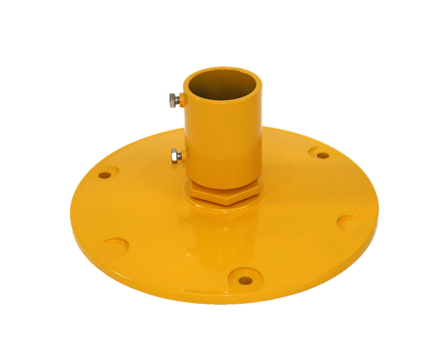
Image disclaimer: For identification and illustration only. It may show a product by another manufacturer and may not depict the exact item described; it is not a statement of any product’s quality, approval or performance. Third-party image and trademark rights belong to their owners. See full notice.
What Is It?
A Base Plate (also known as a mounting plate, fixture plate, or foundation plate) is a robust metal plate that serves as the primary structural interface between an elevated AGL fixture (or other airfield equipment) and the pavement or foundation. It is designed to be securely anchored into the concrete or asphalt, providing a stable, level, and accurately positioned mounting surface for the fixture.
Key characteristics of base plates include:
- Precision Machining: The plate is machined to tight tolerances to ensure that the fixture is perfectly aligned (vertical and horizontal) and that the beam pattern is correctly oriented.
- High Strength: Made from high‑grade steel (often galvanised or stainless) to withstand heavy aircraft loads, impact, and vibration without deformation.
- Corrosion Protection: Hot‑dip galvanised, stainless steel, or coated with anti‑corrosion paint to resist the harsh airfield environment (moisture, de‑icing fluids, fuels).
- Mounting Holes: Pre‑drilled or tapped holes that match the fixture's bolt pattern, allowing for quick and secure attachment.
Base plates are used for a variety of AGL equipment, including:
- Elevated light fixtures: Runway edge lights, taxiway edge lights, approach lights, and obstruction lights.
- Junction boxes and distribution panels: Providing a mounting surface for underground or above‑ground enclosures.
- Signage: For airfield signs and guidance markers.
- Sensor housings: For weather sensors, RVR sensors, and other instrumentation.
The plate is typically embedded in a concrete foundation or directly into the asphalt pavement, with anchor bolts or expansion bolts securing it in place. The top surface of the plate is machined flat and level, and often includes a central hole or conduit entry for cable routing.
Purpose & Function
An elevated fixture's photometric performance depends on it being installed at a specific height, tilt, and orientation — figures decided on a drawing long before the equipment reaches site. The base plate's purpose is to make that specification physically enforceable: a level, precisely machined interface that fixes the fixture's angle and position at installation and keeps it there under the wind loading, vibration, and thermal cycling the fixture experiences afterward. Because the plate carries the full mechanical load from the fixture down into the foundation, it also protects the fixture itself — its housing, optics, and internal wiring are never expected to bear structural loads they were not designed for. In practical terms, the base plate is what turns an engineering drawing's height and angle tolerances into something a technician can actually deliver and trust on site.
Where Is It Used?
Base plates are used throughout the airfield wherever elevated fixtures or equipment require a secure, level, and durable mounting foundation, including:
- Runway Edge Lighting: Providing the foundation for elevated runway edge light fixtures mounted on frangible poles.
- Taxiway Edge Lighting: Mounting elevated taxiway edge light fixtures, especially on curves or where flush mounting is not possible.
- Approach Lighting: Supporting elevated approach light fixtures, barrettes, and flashing light units.
- Obstruction Lighting: Mounting obstruction lights on poles, towers, or building rooftops.
- Airfield Signage: Providing the base for mandatory instruction signs, direction signs, and information signs.
- Junction Boxes and Distribution Panels: Supporting above‑ground enclosures that house cable terminations, connectors, or control equipment.
- Sensor Mounting: For anemometers, wind cones, visibility sensors, and other airfield instrumentation.
The plate is installed during the pavement construction or as a retro‑fit by cutting a recess into the existing pavement. It is leveled using grout or shims, and anchor bolts are torqued to the specified value. The fixture is then bolted to the plate using the pre‑drilled holes. The plate's design ensures that the fixture can be easily removed for maintenance or replacement without disturbing the foundation.
Installation & Location
The base plate sits on top of the foundation or base can, bolted down onto anchor bolts embedded in the concrete, with a levelling check performed before final torque so the pole or fixture mounted on it stands plumb rather than leaning. Plate position and orientation are set out from the fixture's survey point, with any directional fixture's plate keyed or marked so the pole can only be bolted on facing the correct direction. Grouting or shimming under the plate is used where the foundation surface isn't perfectly flat, since an unsupported corner of the plate becomes a stress concentration point under wind or impact loading.
How Does It Work?
The base plate functions as the critical load‑bearing and alignment interface between the fixture and the pavement. Its design ensures that the fixture remains stable, level, and correctly oriented throughout its service life:
- Load Distribution: The plate distributes the weight of the fixture (and any additional loads, such as wind or ice) evenly over a larger area of the pavement, preventing localised stress or cracking.
- Precise Alignment: The machined top surface provides a true reference plane, ensuring that the fixture is perfectly vertical and that the light beam is aimed correctly (e.g., towards the runway centreline or approach path).
- Secure Fixing: Anchor bolts embedded in the foundation secure the plate, while the fixture bolts into the plate's threaded holes. This provides a robust connection that can withstand aircraft jet blast, vibration, and maintenance activities.
- Frangible Feature (if applicable): In some designs, the base plate includes a frangible coupling or shear‑off feature that allows the fixture to break away cleanly on impact, minimizing damage to the aircraft.
The installation process typically involves:
- Setting the plate: The plate is positioned in the wet concrete or asphalt, or bolted into a pre‑formed recess using epoxy anchors.
- Levelling: The plate is adjusted to the correct height and inclination using a spirit level or digital level.
- Grouting: A non‑shrink grout is injected under the plate to fill any voids and provide a solid, level bearing surface.
- Torquing: The anchor bolts are torqued to the manufacturer's specified value to ensure proper clamping force.
- Fixture mounting: The fixture is placed on the plate and secured using the fixture mounting bolts.
The plate is designed to withstand vertical loads (aircraft weight) and horizontal loads (braking, turning, and jet blast) without shifting or deforming. It is typically designed for a minimum service life of 20 years, with regular inspection for corrosion, loose bolts, or damage.
System Architecture & Control Logic
The base plate is a purely mechanical interface with no electrical or control role — it sits between the fixture or pole above and the anchor bolts and foundation below, and its job is to spread the loads from above (dead weight, wind, and any impact) evenly into the bolt pattern rather than concentrating them on one or two fasteners. Its thickness, footprint, and bolt-hole pattern are matched to the specific fixture it carries and to the load case at that installation, which is why it is not a generic, interchangeable part between fixture families even where the anchor bolt spacing happens to match.
A purely mechanical load path — matched to a specific fixture and load case, not a generic interchangeable part.
Installation & Load Path
Physical Construction
A base plate is cut from structural steel, aluminium, or stainless steel plate stock to the thickness required for its rated load, then machined or laser-cut with a bolt hole pattern matched to both the fixture's mounting footprint on top and the anchor bolt layout set into the pavement below. The plate's top and bottom surfaces are finished flat within a tight tolerance so the fixture sits level and true once installed, since even a small deviation can throw off the fixture's beam alignment. Corrosion protection is applied as a hot-dip galvanised coating or powder coat finish over the full plate surface, with threaded holes or captive nuts often protected separately to prevent the coating from interfering with bolt engagement. Where the plate incorporates a frangible coupling interface for elevated fixtures, a weakened section or shear-designed connection point is machined into the plate itself, engineered to fail predictably under an aircraft impact load while retaining full strength under normal wind and vibration loading. The plate is bolted down onto the anchor bolts protruding from the pavement, with levelling nuts or shims used to fine-tune its final position before grouting or backfilling around the base.
Technical Parameters
| Parameter | Typical Value |
|---|---|
| Material | Structural steel (S235JR or S355JR), galvanised or stainless steel (316L) |
| Thickness | 10mm to 25mm (depending on load rating) |
| Dimensions (L x W) | 150mm x 150mm to 400mm x 400mm (varies by fixture) |
| Surface Finish | Hot‑dip galvanised (min 85µm) or powder‑coated |
| Bolt Hole Pattern | Custom to match fixture mounting holes (e.g., 4‑hole, 6‑hole) |
| Anchor Bolt Size | M12 to M24 (depending on load) |
| Load Capacity (vertical) | 10kN to 100kN (depending on plate size and anchoring) |
| Flatness Tolerance | ≤ 0.5mm over the plate area |
| Operating Temperature | -40°C to +85°C |
| Corrosion Resistance | ≥ 500 hours salt spray (galvanised); ≥ 1000 hours (stainless) |
| Standards | EN 10025, ASTM A123, FAA AC 150/5345‑42 |
Applicable Standards
EN 10025
Hot‑rolled products of structural steels (material specification)
ASTM A123
Standard specification for zinc (hot‑dip galvanised) coatings on iron and steel products
FAA AC 150/5345‑42
Specification for Airport Light Bases, Transformer Housings, Junction Boxes, and Accessories
ICAO Annex 14
Physical characteristics of mounting hardware for AGL fixtures
Installation Requirements
Bolt Hole Pattern Match
MechanicalConfirm the plate's bolt hole pattern matches both the fixture's mounting footprint above and the anchor bolt layout below before it is set down, since the two must align simultaneously.
Flatness & Level Verification
MechanicalCheck the plate sits flat and level within tolerance once positioned, since even a small deviation can throw off the fixture's beam alignment once mounted.
Non-Shrink Grout Selection & Placement
CivilUse a non-shrink grout mix rated for the load and inject it fully beneath the plate so no voids remain that could allow settlement under repeated loading.
Anchor Bolt Torque
MechanicalTorque anchor bolts to the value specified for their diameter and grade only after grout has cured, so the plate is not disturbed while the load path is still setting.
Frangible Interface Preservation
MechanicalWhere the plate incorporates a frangible coupling interface, avoid overtightening or damaging the weakened shear section during installation, since it must still fail predictably under an aircraft impact load.
Coating Touch-Up at Threads
MechanicalTouch up any galvanised or powder coating damaged around threaded holes or captive nuts during installation, keeping full bolt engagement while restoring corrosion protection.
Pre-Fixture Sign-off
DocumentationRecord plate level, grout placement, and torque values as-built before the fixture is mounted on top.
Testing & Commissioning
Dimensional & Bolt Hole Pattern Verification
Pre-InstallationConfirm the plate's dimensions and bolt hole pattern match both the fixture's mounting footprint and the anchor bolt layout before installation.
Flatness Tolerance Check
Pre-InstallationVerify the plate's top and bottom surfaces meet the specified flatness tolerance, since deviation here can throw off the fixture's beam alignment once installed.
Levelling Verification
InstallationCheck the plate sits level using a calibrated digital level or spirit level before final bolt-down, adjusting with levelling nuts or shims as needed.
Torque Verification
InstallationTorque the plate's hold-down nuts to the specified value once the fixture is aligned and levelled.
Frangible Section Verification
Pre-InstallationWhere the plate incorporates a frangible coupling interface, confirm the weakened shear section matches the design specification for predictable failure under impact.
Corrosion Coating Inspection
Pre-InstallationVerify the galvanised or powder-coat finish is intact and undamaged before the plate is grouted or backfilled.
Documentation & Sign-off
Final AcceptanceRecord dimensional checks, levelling, and torque results against the installation location in the commissioning dossier.
Inspection & Maintenance
Anchor Bolt Torque Verification
AnnualRe-torque the anchor bolts securing the plate to spec so it maintains its rated load capacity and stays firmly seated against the foundation.
Flatness Check
AnnualVerify the plate remains within its ≤0.5 mm flatness tolerance; a warped plate can introduce uneven stress on the mounted fixture and its coupling.
Corrosion / Coating Check
AnnualInspect galvanised or powder-coated surfaces for coating breakdown or pitting, particularly around bolt holes where moisture tends to collect.
Bolt Hole Wear Check
AnnualInspect bolt holes for elongation or cracking under repeated vibration loading, which can gradually loosen the fixture connection over time.
Foundation Interface Check
AnnualCheck for cracking or settlement in the surrounding concrete or pavement that could affect plate levelness and load transfer.
Deformation / Load Rating Check
AnnualLook for bending or deformation under load, particularly on thinner plates near the upper end of their load rating.
Alignment Check
AnnualConfirm the bolt hole pattern remains correctly aligned with the fixture mounting holes, especially after any resurfacing or fixture replacement.
Vibration Looseness Check
Semi-annualCheck for play or rocking between the plate and mounted fixture, an early sign of bolt or hole wear before failure occurs.
Common Field Issues
Corrosion of Plate and Bolts
Base plates are exposed to moisture, de‑icing chemicals, and fuels. Galvanised coatings can be damaged during installation, leading to rust. Use stainless steel plates or apply additional protective coatings. Regularly inspect and touch up damaged areas.
Loose Anchor Bolts
Vibration from aircraft and thermal cycling can cause anchor bolts to loosen, resulting in fixture misalignment or instability. Use torque wrenches during installation and schedule periodic re‑torquing as part of maintenance.
Poor Levelling
If the plate is not level, the fixture's beam pattern will be incorrect, reducing visibility for pilots. Use a precision level and shim the plate as needed. Grout under the plate to ensure full contact and support.
Inadequate Grouting
Voids under the plate can lead to stress concentrations, causing the plate to crack or the pavement to fail. Use non‑shrink grout and ensure it is fully injected to fill all voids.
Misalignment with Fixture
If the plate's bolt holes do not align with the fixture, the fixture may be forced into position, causing stress or incorrect orientation. Verify the bolt pattern before installation and use adjustable plates where necessary.
Damage from Snowploughs or Maintenance Vehicles
Base plates installed on runways or taxiways can be struck by snowploughs or maintenance vehicles. Use recessed or low‑profile plates, and install protective covers if possible.
Incorrect Anchor Bolt Depth
If the anchor bolts are not embedded to the required depth, they may not provide sufficient pull‑out strength. Follow the manufacturer's specifications for embedment depth and torque.
Troubleshooting Guide
Visible Rust on Plate or Bolts
Fixture Loose or Misaligned
Fixture Beam Aimed Incorrectly
Plate Cracking or Pavement Failure Around the Base
Fixture Forced or Stressed During Installation
Plate Damaged or Displaced
Anchor Bolts Pulling Loose or Failing Under Load
Failure Modes & Root Causes
Corrosion of Plate and Bolts
Loose Anchor Bolts
Poor Levelling
Inadequate Grouting
Damage from Snowploughs or Maintenance Vehicles
Misalignment with Fixture
Safety & Operational Notes
Verify Isolation Before Removal
Electrical SafetyWhere the base plate carries the fixture's bonding/earth connection, de-energise and lock out the associated circuit and verify zero energy before disconnecting or lifting the plate.
Correct Fastener Torque
MechanicalTorque mounting bolts to specification; an under-torqued plate can work loose under vibration and shift fixture aim, while over-torquing can distort the plate or interfere with a frangible coupling's designed shear threshold.
Frangibility Not to Be Compromised
MechanicalNever add reinforcement, shims, or a stiffer plate than specified where the base plate forms part of a frangible assembly; doing so can raise the impact force needed to break away and defeat the safety design.
Level & Alignment Check
ComplianceVerify the plate is level and correctly orientated before final tightening, since a tilted base plate carries through to fixture aim and can put the light out of photometric tolerance.
Airside Work Coordination
OperationalCoordinate with ATC/airside and raise a NOTAM where the fixture will be out of service or out of tolerance during the work.
FOD Control
OperationalAccount for all fasteners, shims, and washers on the movement area, and clear the work site fully before reinstating the fixture.
PPE & Grounding
Personnel SafetyUse insulated tools where the plate is part of a live-circuit bonding path, and confirm bonding continuity is restored before reconnecting the fixture.
Engineering & Expert Notes
Shimming Corrects Level But Can Mask an Underlying Foundation Problem
AlignmentAdding shims to level a base plate after installation is a legitimate fix for minor foundation irregularity, but repeated or heavy shimming at the same location often signals a settlement or pour-quality issue that will keep recurring. Investigate the foundation itself if shimming needs are increasing over time.
Re-Verify Machined Tolerance After Any Rework
PrecisionIf a base plate is drilled, welded, or otherwise modified in the field to fit a non-standard situation, its original machined flatness and hole-position tolerances are no longer guaranteed. Re-check alignment tolerances after any field modification rather than assuming factory precision still holds.
Check the Underside, Not Just the Visible Top Surface
CorrosionThe underside of a base plate sits against the foundation or can and traps moisture against bare or damaged coating far longer than the exposed top surface; corrosion often starts there and isn't visible until the plate is lifted during other maintenance work.
Confirm Bonding Continuity After Any Plate Replacement
ElectricalWhere the base plate forms part of the fixture's bonding/earthing path, a replacement plate installed with fresh paint or coating at the bonding point can silently break electrical continuity even though it looks correctly bolted down. Verify continuity with a meter after any plate swap.
Torque Pattern Matters as Much as Torque Value
MechanicalTightening base plate bolts in the wrong sequence can induce a slight warp in the plate even when every bolt reaches the correct final torque value. Follow a cross-pattern tightening sequence, especially on larger plates with more than four fixing points.
Record As-Installed Shim Configuration for Future Reference
DocumentationWhen shims are used to achieve level, document their thickness and position at commissioning; this baseline makes it much faster to distinguish new settlement from the original, accepted correction during a future inspection.
Frequently Asked Questions
Short answers about the base plate: what it is, how it works, specifications, standards, maintenance and common faults.
Q1What is a base plate in airfield ground lighting?
A base plate (also called a mounting plate, fixture plate or foundation plate) is a robust metal plate that forms the structural interface between an elevated AGL fixture, or other airfield equipment, and the pavement or foundation. It gives a stable, level and accurately positioned mounting surface.
Q2What does a base plate do?
It distributes the fixture's weight and any wind or ice loads over a larger area of pavement, provides a machined reference plane so the fixture is vertical and its beam is correctly aimed, and is secured by anchor bolts embedded in the foundation.
Q3Where are base plates used?
They are used under elevated runway edge light fixtures on frangible poles, elevated taxiway edge lights, elevated approach lights, and other elevated fixtures and equipment that need a secure, level, durable mounting foundation.
Q4What are the typical dimensions and materials?
Thickness is typically 10 mm to 25 mm and size 150 mm x 150 mm to 400 mm x 400 mm depending on the fixture. Material is structural steel (S235JR or S355JR), galvanised or 316L stainless, with anchor bolts from M12 to M24 and hole patterns such as 4-hole or 6-hole to match the fixture.
Q5How flat must a base plate be?
Flatness tolerance is typically 0.5 mm or better over the plate area. Poor levelling or inadequate grouting can leave the fixture out of alignment.
Q6What load can a base plate carry, and how is it protected from corrosion?
Typical vertical load capacity is 10 kN to 100 kN depending on plate size and anchoring. The finish is hot-dip galvanising of at least 85 µm or powder coating, with salt spray resistance of at least 500 hours for galvanised and 1,000 hours for stainless.
Q7Which standards apply to base plates?
The main references are EN 10025 (structural steel), ASTM A123 (galvanised coatings), FAA AC 150/5345-42 (light bases and accessories) and ICAO Annex 14. Always verify the current edition and your aerodrome's approved requirements.
Q8How often should a base plate be inspected?
Typical annual checks cover anchor bolt torque, flatness, corrosion and coating, bolt hole wear, foundation interface, deformation and load rating, and alignment, with a semi-annual vibration looseness check. Your airport's approved maintenance programme takes precedence.
Q9What are the common problems with base plates?
Common problems are corrosion of the plate and bolts, loose anchor bolts, poor levelling, inadequate grouting, misalignment with the fixture, damage from snowploughs or maintenance vehicles and incorrect anchor bolt depth. A loose or misaligned fixture, or a badly aimed beam, is a sign to check the plate and its anchoring.
Related Components
Go Beyond the Component. Understand the Complete AGL System.
You have explored the component. Now understand how it works within the complete Airfield Ground Lighting system.
Learn AGL from fundamentals to design, installation, testing, photometry, commissioning, maintenance and troubleshooting through structured technical training at Precision AGL Academy.
Build practical knowledge. Understand the circuit. Read the standards. Troubleshoot with confidence.
Your next step in AGL starts here.
Need expert guidance on base plate selection and installation for your AGL project?
Precision AGL Academy provides advice on material selection, corrosion protection, levelling techniques, and anchoring for secure and durable fixture mounting.
Follow the Academy
Important Notice, Disclaimer & Limitation of Liability
Please read before relying on any content on this page.
- Purpose and intended users. This page on Base Plate is an independent educational and informational reference for competent, suitably trained and authorised airfield ground lighting (AGL) and aerodrome electrical personnel. It is not professional engineering, legal or regulatory advice, and using it does not create any professional or client relationship.
- Safety. Work on series circuits, constant current regulators (CCRs), isolating transformers, cables, connectors and lighting equipment can be fatal. Always apply the aerodrome’s permit-to-work and isolation/LOTO procedures, prove dead, use correctly rated instruments and PPE, and follow the manufacturer’s instructions. Nothing here authorises work on live equipment or the bypassing of any safety device or interlock.
- Aviation operations. Nothing here authorises installation, modification, energisation, adjustment, return to service, a change of operating category (CAT I/II/III), a NOTAM or any aerodrome certification or approval decision. These rest with the aerodrome operator, the air navigation service provider and the competent regulator.
- Specifications, ratings and typical values. Descriptions, parameters, ratings, dimensions, photometric values, wattages, service lives, maintenance tasks and intervals, failure modes, certifications (for example CE, FCC, UL or IEC marks) and part or type designations are general, typical and indicative. They may not match any particular product, make, model or version, and they are not a datasheet, design, specification, selection, sizing, procurement or acceptance criterion. The manufacturer’s current documents, the approved design and the project specification prevail.
- Standards and regulations. References to ICAO, FAA, IEC, IEEE, ISO, BIS, DGCA and other standards are paraphrased summaries for orientation only. They may be incomplete or out of date, and standards are revised from time to time. Consult the current official editions. Following this content does not guarantee compliance with any law, standard or regulatory approval, and the regulator’s requirements always prevail.
- No warranty. Content is provided “as is” and “as available”, without warranty of any kind, express or implied, including accuracy, completeness, currency or fitness for a particular purpose. Real installations differ in design, equipment make and model, age and condition.
- Limitation of liability. To the fullest extent permitted by applicable law, Precision AGL Academy, Precision AGL Solutions and their owners, authors and contributors are not liable for any injury, death, loss, damage, downtime, penalty or regulatory consequence, whether direct or indirect, arising from the use of, reliance on, or inability to use this content. Nothing in this notice excludes or limits any liability that cannot lawfully be excluded or limited.
- Independence, brands and no endorsement. This is an independent publication. It is not affiliated with, sponsored by or endorsed by ICAO, the FAA, the IEC, DGCA, AAI, any airport, regulator, supplier or equipment manufacturer. Third-party names, product designations, standard designations and trademarks (including Megger®, Siemens, Eaton, Crouse-Hinds, ADB SAFEGATE, Fluke, ABB and Honeywell) belong to their respective owners and are used only for identification and description. Mention of a brand, product or supplier is not a recommendation, and we do not sell, supply or quote for any component described.
- Images and third-party content. Images and illustrations are shown to help identify the type of component. They may show products of various manufacturers, may not depict the exact item described, and are not a statement about any product’s quality, approval or performance. Copyright and trademarks in third-party images, logos and photographs belong to their respective owners and are not claimed as ours. If you are a rights holder and want an image removed, replaced or credited, email precisionaglsolutions@gmail.com with the page address and we will act promptly.
- Training and services. Mentions of training, courses, consultation, advice, selection, installation, calibration or other support, including the “Learn…Certify” pathway, describe learning stages and are not an offer, quotation, tender or promise of any result. Contacting us or our replying creates no engagement or duty of care; an engagement exists only under a written agreement. We are not a regulator or certification body, and completing any course or reading this content is not a certification, accreditation or authorisation to work on any aerodrome.
- Copyright, privacy and corrections. © 2026 Precision AGL Academy. All rights reserved. Text, structure, compilations and diagrams may be viewed for personal reference and internal training only; any other copying, republication or commercial use needs our written permission. If you email, telephone or message us, we use your details only to respond and handle your matter, in line with applicable Indian law including the Digital Personal Data Protection Act, 2023; please do not send confidential or security-sensitive information. To display this page your browser requests fonts, icons and images from third-party servers, which receive your IP address and browser details under their own policies. Content is reviewed periodically with no obligation to update. To report an error, safety concern or rights issue, write to precisionaglsolutions@gmail.com.