Series‑Circuit Junction Box
A robust, waterproof enclosure used to house cable splices, terminations, and test points in the AGL primary and secondary series circuits. Designed for buried, handhole, or surface‑mount installation, it provides mechanical protection, environmental sealing, and safe access for maintenance and testing of the constant‑current series loop.
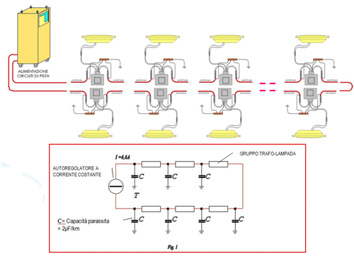
Image disclaimer: For identification and illustration only. It may show a product by another manufacturer and may not depict the exact item described; it is not a statement of any product’s quality, approval or performance. Third-party image and trademark rights belong to their owners. See full notice.
What Is It?
The Series‑Circuit Junction Box is a robust, weatherproof enclosure used in airfield ground lighting (AGL) systems to house cable splices, terminations, test points, and transitions in the primary and secondary series circuits. It provides a protected environment for electrical connections, ensuring long‑term reliability and providing safe access for maintenance, testing, and fault diagnosis.
Key characteristics of series‑circuit junction boxes include:
- Waterproof Construction: IP68‑rated enclosures that protect internal connections from moisture, dirt, and corrosion in buried or handhole installations.
- Durable Materials: Manufactured from high‑strength materials such as glass‑reinforced polyester, polycarbonate, brass, or stainless steel to withstand mechanical loads, UV exposure, and chemical attack.
- Multiple Cable Entries: Equipped with cable glands, knockouts, or compression seals to accommodate primary (L‑824) and secondary cables of various sizes.
- Internal Mounting: Includes mounting rails, terminal blocks, earth bars, and cable tie points for organising and securing internal connections.
- Accessibility: Designed with removable covers or hinged lids for easy access during installation, inspection, and maintenance.
Junction boxes are installed at strategic points along the series circuit, including at cable splices, circuit transitions, test points, and equipment interfaces. They are essential for maintaining the integrity of the AGL system and enabling efficient maintenance and fault diagnosis.
Purpose & Function
The junction box's purpose is to turn what would otherwise be a bare, buried cable splice into an accessible, protected node that can be tested, inspected, and repaired without excavating the surrounding trench. Because a series circuit's reliability depends on every splice and termination along its length staying watertight and mechanically sound, concentrating those connections inside a sealed, organised enclosure rather than leaving them wrapped in the open ground is what allows a fault to be isolated to a specific section of cable during troubleshooting instead of requiring the entire loop to be dug up to find it. Positioning boxes at cable splices, transitions, and test points also means routine circuit testing can happen at known, accessible locations, rather than needing to locate a splice point from as-built drawings before any diagnostic work can begin.
Where Is It Used?
Series‑circuit junction boxes are used throughout the airfield at key points in the AGL system, including:
- Cable Splice Locations: Housing splices where primary or secondary cables are joined to extend the circuit length or repair damage.
- Test Points: Providing accessible test terminals for measuring current, voltage, and insulation resistance at regular intervals along the series loop.
- Circuit Transition Points: At the interface between underground and elevated cable sections, providing a protected environment for cable transitions.
- Transformer Connections: Some junction boxes are used to house the primary and secondary connections to isolating transformers, especially in underground transformer installations.
- Tap‑Off and Branch Points: Where a branch circuit is taken from the main series loop (e.g., to feed a separate lighting segment).
- CCR Output Interface: At the output of the Constant Current Regulator, where primary cables are connected to the field distribution system.
- Equipment Interfaces: At the connection points between the AGL system and other equipment such as control panels, monitoring systems, and alarm panels.
Junction boxes are available in various sizes and configurations to suit the specific application, from small boxes for single splices to large enclosures with multiple cable entries and internal mounting provisions for complex circuits.
Installation & Location
These junction boxes are installed at whichever point in the series loop needs a splice, test point, or transition — buried in a handhole or pit at cable joins and transformer connections, set into the ground at regular intervals along the loop to provide test access, or mounted where an underground run transitions to an elevated structure or building entry. Box size and configuration are chosen to match the application, from a small single-splice enclosure buried flush with grade to a larger multi-entry box at a CCR output or equipment interface. Placement is tied into the same cable route and survey used for the rest of the circuit, keeping the box accessible for testing and maintenance without needing to trace buried cable to locate it.
How Does It Work?
A series‑circuit junction box provides a protected environment for electrical connections, ensuring reliability and enabling maintenance. Its design incorporates several functional elements:
- Enclosure: The rigid housing protects internal connections from physical damage, moisture, and contaminants. The IP68 rating ensures that the enclosure remains watertight even when submerged in water or buried in wet soil.
- Cable Entries: Cable glands or compression seals provide watertight entry for cables, preventing moisture from tracking along the cable jacket into the enclosure. Glands are sized to match the cable diameter.
- Internal Mounting: Mounting rails or plates allow the installation of terminal blocks, earth bars, and cable ties to organise and secure internal connections. This prevents strain on the connections and facilitates maintenance.
- Earthing/Bonding: An internal earth bar provides a common grounding point for cable screens, equipment earthing, and the enclosure itself, ensuring electrical safety and EMI protection.
- Test Access: Many junction boxes include test points or probe ports that allow connection of test instruments without opening cable splices or disturbing terminations.
- Identification: Clear marking of the enclosure, cable entries, and internal connections aids maintenance and reduces the risk of errors during work.
When properly installed and sealed, the junction box provides a reliable, long‑life housing for AGL circuit connections, withstanding the harsh airfield environment including temperature extremes, moisture, chemical exposure, and mechanical loads.
System Architecture & Control Logic
A series-circuit junction box has no control logic of its own — like a connector or a transformer housing, its role in the system's architecture is structural rather than active. It sits inside the same series circuit the CCR regulates and monitors, providing a protected point where that circuit can be spliced, branched, transitioned between underground and elevated runs, or accessed for testing, without ever itself issuing a command or making a decision about the circuit's state.
What the box does contribute to the system's control architecture is accessibility: because test points are placed at known, documented locations rather than left as bare splices, a technician can verify current, voltage, or insulation resistance at that exact point in the loop — closing a manual diagnostic loop around a specific circuit section — while the CCR's own automatic fault detection continues to watch the whole loop for the same voltage-versus-current deviation it would flag anywhere else.
CCR / Series Circuit → Junction Box (splice, transition, test point) → Downstream Circuit (loop-level feedback)
Where It Sits in the Circuit
Series-Circuit Junction Box
Protected enclosure for connections along the loop
CCR Output Interface
Primary cable connects to the field distribution system
Cable Splices
Joins to extend circuit length or repair damage
Test Points
Accessible terminals for current, voltage & insulation checks
U/G ↔ Elevated Transitions
Protected interface between buried & elevated cable runs
Transformer Connections
Primary/secondary terminations at underground transformers
Tap-Off / Branch Points
Where a branch circuit is taken from the main series loop
Protected, Testable Connections at Every Key Point
Maintains circuit integrity and enables fault diagnosis without disturbing splices
Physical Construction
The enclosure is typically a glass-reinforced polymer, cast resin, or corrosion-treated metal box, sized to give working clearance around the splices it houses and rated to at least IP67 given its frequent below-grade or in-pit installation. Cable entries are formed as sealed glands or a gel-filled entry plate on each face, sized for the primary and secondary conductor diameters and positioned so cables enter without sharp bends that could stress the termination. Splices and terminations inside are made with insulated, moisture-resistant connectors — often resin-encapsulated or heat-shrink sealed for the primary series-circuit joint specifically — mounted on a terminal rail or potted directly into the box body for extra security against vibration and settlement. The lid seats on a full-perimeter gasket and is secured with corrosion-resistant fasteners or a locking mechanism, and where the box also serves as a test point, dedicated test terminals are brought to an accessible face so current and insulation-resistance testing can be carried out without disturbing the sealed splices themselves.
Technical Parameters
| Parameter | Typical Value |
|---|---|
| Material | Glass‑reinforced polyester (GRP), polycarbonate, brass, or stainless steel |
| Protection Class | IP68 (submersible, continuous) |
| Operating Temperature | -40°C to +85°C |
| Cable Entry Types | Compression glands, knockouts, or cable seals |
| Cable Size Compatibility | Primary: 6 AWG to 2 AWG; Secondary: 1.5mm² to 6mm² |
| Internal Mounting | Mounting rails, terminal blocks, earth bars |
| Cover Type | Removable lid with gasket, hinged with quick‑release fasteners |
| Voltage Rating | 5kV (primary insulation), 600V (secondary) |
| Current Rating | 6.6A or 20A (series circuit rating) |
| Typical Sizes | 150×150×100mm to 600×400×200mm (custom sizes available) |
| Colour | Black, grey, or green (custom colours available) |
| Standards | IEC 60529, IEEE 404, FAA AC 150/5345‑7 (L‑824 cable) |
Electrical Requirements
| Requirement | Typical Value |
|---|---|
| Circuit Type | In-line junction on the series constant-current lighting circuit (not a branch/parallel connection) |
| Voltage Rating | 5kV (primary insulation), 600V (secondary) |
| Current Rating | 6.6A or 20A (series circuit rating), matching the circuit it is installed on |
| Internal Wiring | Terminal blocks and earth bars sized to the primary/secondary cable ratings above |
| Insulation Resistance | ≥ 50 MΩ (megger test, cable-to-ground, measured at the terminal blocks) |
| Earthing/Grounding | Integrated earth bar bonded to the airfield earth grid; enclosure bonded where metallic |
| Cable Entry | Glanded/sealed entries sized to maintain the box's IP68 rating with cables installed |
| Fault Protection | Isolation for maintenance is via the associated CCR; the box itself has no independent protective device |
Applicable Standards
IEC 60529
Degrees of protection provided by enclosures (IP Code) — IP68 rating
IEEE 404
Electrical ratings and test requirements for shielded power-cable joints/splice kits — relevant where a splice inside the box is rated above the L-824 series-circuit range
FAA AC 150/5345‑7 & ‑26
Specification for L‑824 underground cable and L‑823 plug/receptacle connectors used in the series circuit
ICAO Annex 14
General requirements for AGL circuit components and installation
Installation Requirements
Enclosure Excavation or Mounting
CivilExcavate and set the box to grade for a buried or in-pit installation, or fix the mounting bracket for a structure-transition box, sizing the position for the splice count and cable diameters it will carry.
Position Tied to Cable Survey
CivilSite the box on the same cable route and survey used for the rest of the circuit, keeping it accessible for testing and maintenance without needing to trace buried cable to locate it.
Cable Entry & Bend Radius
ElectricalRoute primary and secondary cables through the sealed glands or gel-filled entry plate so each enters without sharp bends that could stress the termination.
Splice & Termination
ElectricalMake splices with insulated, moisture-resistant connectors — resin-encapsulated or heat-shrink sealed for the primary series-circuit joint — mounted on the terminal rail or potted into the box body.
Test Terminal Provision
ElectricalWhere the box also serves as a test point, bring dedicated test terminals to an accessible face so current and insulation-resistance testing can be carried out without disturbing the sealed splices.
Lid Gasket Seal
MechanicalSeat the lid on its full-perimeter gasket and secure it with the corrosion-resistant fasteners or locking mechanism, confirming the enclosure meets its IP67 rating before backfill or handover.
Working Clearance Check
MechanicalConfirm working clearance around the splices inside the box before closing it, since space is sized to the number and type of terminations it houses.
Pre-Closure Sign-off
DocumentationRecord box position, splice details, and cable route as-built before the lid is closed and backfill or reinstatement proceeds, since these are not inspectable afterward.
Testing & Commissioning
Insulation Resistance Test
Pre-EnergisationMegger-test through the completed junction box termination before backfill, confirming insulation resistance clears the acceptable minimum.
Continuity & Loop Resistance Test
Pre-EnergisationVerify series loop continuity through the box and record loop resistance, ruling out a poorly made connection at the terminal block.
IP68 Seal & Ingress Test
Pre-EnergisationConfirm lid gaskets and cable gland seals are correctly fitted, and pressure- or water-test the enclosure where required before burial.
Terminal Torque Verification
Pre-EnergisationTorque every terminal connection inside the box to the manufacturer's specification and mark each as checked.
Primary Voltage Verification
EnergisationWith the CCR energised, confirm voltage is present and correctly regulated across the junction box's through-connections.
Documentation & As-Built Sign-off
Final AcceptanceRecord insulation, continuity, and seal test results alongside the box's as-built location in the commissioning dossier for handover.
Inspection & Maintenance
Seal & Gasket Inspection
AnnualCheck the lid gasket and cable seals for cracking or compression set, and re-fasten quick-release fittings to spec to keep the box watertight to its IP68 rating.
Terminal Block & Earth Bar Check
AnnualRe-torque terminal block and earth bar connections to spec, since a loose splice inside the box is a common source of series-circuit faults.
Insulation Resistance Test
AnnualMegger-test connections inside the box to confirm insulation resistance stays above the minimum, flagging moisture ingress before it causes a loop fault.
Cable Entry & Gland Check
AnnualConfirm compression glands and knockouts remain properly sealed around each cable entry, especially after any re-cabling work.
Corrosion & Enclosure Condition Check
AnnualInspect the enclosure material and any metallic fittings for corrosion, UV degradation, or physical damage.
Standing Water Check
Semi-annualOpen the box during scheduled maintenance to confirm no standing water has accumulated internally despite the IP68 seal.
Pit/Surround Condition Check
AnnualCheck the surrounding pavement, turf, or pit for settlement, cracking, or debris that could affect access or drainage around the box.
Labelling & Circuit Identification Check
AnnualConfirm internal circuit and cable labelling remains legible so field technicians can identify connections quickly during fault-finding.
Common Field Issues
Water Ingress Through Cable Glands
If cable glands are not properly tightened or are the wrong size for the cable, moisture can enter the enclosure. Regularly inspect and tighten glands, and ensure they are correctly sized for the cable diameter.
Corrosion of Enclosure and Components
In aggressive environments (coastal, industrial), the enclosure and internal components can corrode. Use corrosion‑resistant materials (stainless steel, brass, or GRP) and apply protective coatings where necessary.
Damaged or Missing Gaskets
If the lid gasket is damaged or missing, the enclosure will not maintain its IP rating. Inspect gaskets regularly and replace if cracked, compressed, or degraded.
Inadequate Cable Strain Relief
If cables are not properly secured inside the enclosure, tension on the cables can pull on internal terminations, causing high‑resistance connections. Use cable ties and strain relief brackets to secure cables.
Insufficient Internal Space
Overcrowded enclosures make maintenance difficult and increase the risk of damage to cables and connections. Always select an enclosure size that provides adequate space for the number of cables and terminations.
Loose or High‑Resistance Connections
Terminal connections inside the junction box can loosen due to vibration or thermal cycling. Periodically check and tighten all connections as part of routine maintenance.
Inaccessible Location
Junction boxes that are buried too deep, covered by asphalt, or obstructed by equipment can be difficult to access for maintenance. Ensure boxes are installed at accessible depths and that their locations are clearly marked.
Troubleshooting Guide
Corrosion or Moisture Found Inside the Box
Enclosure Fails to Hold Its IP Rating
Intermittent Fault or High-Resistance Reading at a Termination
Corrosion of Enclosure Body or Fittings
Box Difficult to Locate or Access for Maintenance
Failure Modes & Root Causes
Gasket Seal Degradation / Water Ingress
IP Rating Failure at Cable Entries
High-Resistance Termination
Enclosure Body / Fitting Corrosion
Buried or Obstructed Box
Safety & Operational Notes
Series Circuit Isolation
Electrical SafetyThe box houses splices and test points carrying constant-current series loop power that can reach several kV. De-energise and lock out the CCR, then verify zero energy at the box before opening it or handling connections inside.
Confirm the Correct Box Before Isolating
OperationalOn circuits with several junction boxes in series, positively identify the correct box before isolating work, since opening the wrong one can leave live conductors exposed while the intended section stays dark.
Insulation Test Before Re-Energisation
Electrical SafetyAfter any splice, termination, or test-point work, megger test the affected circuit before restoring power, since a residual fault at re-energisation can trip the CCR or damage healthy fixtures on the same circuit.
PPE & Grounding
Personnel SafetyUse insulated tools and appropriate PPE when working on series-circuit connections, and confirm the box and cable shielding are bonded/grounded per the electrical design before reconnecting.
Maintain IP68 Integrity
Electrical SafetyRenew gaskets and properly seat cable glands and the cover on reassembly to preserve the enclosure's IP68 rating, particularly on buried or handhole installations where a compromised seal is hard to detect until a fault develops.
FOD Control at the Enclosure
OperationalKeep tools, fasteners, and removed gaskets accounted for at all times when the box is open, and secure or remove any loose material before closing it, to prevent foreign object debris on the movement area.
Buried or Handhole Access
OperationalFollow the aerodrome's permit-to-dig and pit-access procedures where the box is buried or set in a handhole, and check for water or debris accumulation before opening it.
Restore to Compliant State
ComplianceDo not leave a junction box with a loose connection, an unsealed gland, or a mis-seated cover after maintenance; verify insulation resistance and secure closure before closing out the work order.
Engineering & Expert Notes
Identical-Looking Boxes Along a Loop Are a Mis-Isolation Risk
OperationalOn a long series circuit with multiple similar junction boxes, relying on memory or a rough count to find "the right one" invites opening a live box while the intended section stays dark; mark box identifiers clearly and cross-check against as-built records before isolating.
IP68 Failure Is Progressive, Not Binary
DurabilityA gasket or gland that's slightly degraded doesn't fail all at once; it allows gradual moisture ingress that can take months to manifest as an insulation fault, so a box that's been open longer than a quick visit deserves a fresh gasket rather than reuse of the old one on principle.
Trend Insulation Readings at Each Box Independently
TroubleshootingA long series loop with several junction boxes can have one box slowly developing a fault while the loop as a whole still tests within tolerance at the CCR; testing at each box individually, and trending those readings over time, localises a developing problem long before it takes the loop down.
Handhole Boxes Need a Standing-Water Check Before Opening
EnvironmentalOpening a handhole box that has accumulated standing water without first checking and pumping it down risks water entering the box the moment the lid comes off; always check and clear standing water in the pit before breaking the seal, not just before working inside.
Splice Point Density Along a Loop Affects Fault-Finding Time
DesignA loop with many closely spaced junction boxes is faster to isolate a fault within but has more total seal points at risk; when adding a new tap or splice, weigh this trade-off rather than defaulting to the nearest convenient box.
Record Box-Specific Insulation History, Not Just Circuit-Wide Results
ComplianceA circuit-wide megger reading taken at the CCR end can mask which specific box is trending toward failure; keep insulation resistance records by individual box location so a developing fault can be traced to a specific point rather than the whole loop.
Related Components
Frequently Asked Questions
Short answers about series-circuit junction boxes: purpose, construction, ratings, standards and maintenance.
Q1What is a series-circuit junction box?
It is a robust, waterproof enclosure that houses cable splices, terminations, test points and transitions in AGL primary and secondary series circuits. It can be buried, installed in a handhole or surface-mounted, and gives protected, accessible connections for maintenance, testing and fault diagnosis.
Q2What is the purpose of a series-circuit junction box?
It turns a bare buried splice into a protected node that can be tested, inspected and repaired without excavating the trench. Because a series circuit depends on every splice staying watertight and sound, concentrating connections in a sealed enclosure lets a fault be isolated to a specific cable section.
Q3Where are series-circuit junction boxes used?
At cable splices, test points along the loop, transitions between underground and elevated cable, underground transformer connections, tap-off and branch points, the CCR output interface and equipment interfaces with control, monitoring and alarm panels.
Q4What are junction boxes made of, and how are they sealed?
Common materials are glass-reinforced polyester (GRP), polycarbonate, brass or stainless steel. The enclosure is IP68 (submersible, continuous), with compression glands, knockouts or cable seals at the entries and a removable or hinged lid with a gasket.
Q5What is inside a series-circuit junction box?
Mounting rails or plates, terminal blocks, an earth bar bonded to the airfield earth grid, and cable tie points for securing connections. Many boxes also have test points or probe ports so instruments can connect without opening splices, and clear labelling of circuits and cable entries.
Q6What are typical junction box specifications?
Insulation is rated 5 kV for primary and 600 V for secondary, with a series circuit current rating of 6.6 A or 20 A. Cable compatibility is primary 6 AWG to 2 AWG and secondary 1.5 mm² to 6 mm². Typical sizes range from 150×150×100 mm to 600×400×200 mm.
Q7Does a junction box have its own protection?
No. Isolation for maintenance is through the associated CCR, and the box itself has no independent protective device. Insulation resistance measured cable-to-ground at the terminal blocks should be at least 50 MΩ.
Q8Which standards apply to series-circuit junction boxes?
The main references are IEC 60529 (IP code), IEEE 404 (shielded power-cable joints, relevant where a splice is rated above the series-circuit range), FAA AC 150/5345-7 and -26 (L-824 cable and L-823 connectors) and ICAO Annex 14. Always verify the current edition.
Q9How often should a junction box be inspected?
Annually: seal and gasket inspection, terminal block and earth bar torque, insulation resistance test, gland checks, corrosion checks, pit surround condition and label legibility. Semi-annually, open the box to check for standing water. Your airport's approved maintenance programme takes precedence.
Q10What are the common junction box problems?
Water ingress through loose or wrongly sized glands, corrosion in aggressive environments, damaged or missing gaskets, inadequate cable strain relief, overcrowded enclosures, loose or high-resistance connections from vibration or thermal cycling, and boxes buried too deep or covered by asphalt.
Q11What safety steps apply when working in a junction box?
The box can carry constant-current series loop power reaching several kV, so de-energise and lock out the CCR and verify zero energy. On circuits with several boxes in series, positively identify the correct one first, follow permit-to-dig and pit-access procedures, and megger test the circuit before re-energising. Renew gaskets and seat glands and the cover properly to preserve IP68.
Go Beyond the Component. Understand the Complete AGL System.
You have explored the component. Now understand how it works within the complete Airfield Ground Lighting system.
Learn AGL from fundamentals to design, installation, testing, photometry, commissioning, maintenance and troubleshooting through structured technical training at Precision AGL Academy.
Build practical knowledge. Understand the circuit. Read the standards. Troubleshoot with confidence.
Your next step in AGL starts here.
Need expert guidance on series‑circuit junction box selection and installation for your AGL project?
Precision AGL Academy provides advice on enclosure selection, cable entry configurations, and best practices for reliable AGL circuit protection.
Follow the Academy
Important Notice, Disclaimer & Limitation of Liability
Please read before relying on any content on this page.
- Purpose and intended users. This page on Series‑Circuit Junction Box is an independent educational and informational reference for competent, suitably trained and authorised airfield ground lighting (AGL) and aerodrome electrical personnel. It is not professional engineering, legal or regulatory advice, and using it does not create any professional or client relationship.
- Safety. Work on series circuits, constant current regulators (CCRs), isolating transformers, cables, connectors and lighting equipment can be fatal. Always apply the aerodrome’s permit-to-work and isolation/LOTO procedures, prove dead, use correctly rated instruments and PPE, and follow the manufacturer’s instructions. Nothing here authorises work on live equipment or the bypassing of any safety device or interlock.
- Aviation operations. Nothing here authorises installation, modification, energisation, adjustment, return to service, a change of operating category (CAT I/II/III), a NOTAM or any aerodrome certification or approval decision. These rest with the aerodrome operator, the air navigation service provider and the competent regulator.
- Specifications, ratings and typical values. Descriptions, parameters, ratings, dimensions, photometric values, wattages, service lives, maintenance tasks and intervals, failure modes, certifications (for example CE, FCC, UL or IEC marks) and part or type designations are general, typical and indicative. They may not match any particular product, make, model or version, and they are not a datasheet, design, specification, selection, sizing, procurement or acceptance criterion. The manufacturer’s current documents, the approved design and the project specification prevail.
- Standards and regulations. References to ICAO, FAA, IEC, IEEE, ISO, BIS, DGCA and other standards are paraphrased summaries for orientation only. They may be incomplete or out of date, and standards are revised from time to time. Consult the current official editions. Following this content does not guarantee compliance with any law, standard or regulatory approval, and the regulator’s requirements always prevail.
- No warranty. Content is provided “as is” and “as available”, without warranty of any kind, express or implied, including accuracy, completeness, currency or fitness for a particular purpose. Real installations differ in design, equipment make and model, age and condition.
- Limitation of liability. To the fullest extent permitted by applicable law, Precision AGL Academy, Precision AGL Solutions and their owners, authors and contributors are not liable for any injury, death, loss, damage, downtime, penalty or regulatory consequence, whether direct or indirect, arising from the use of, reliance on, or inability to use this content. Nothing in this notice excludes or limits any liability that cannot lawfully be excluded or limited.
- Independence, brands and no endorsement. This is an independent publication. It is not affiliated with, sponsored by or endorsed by ICAO, the FAA, the IEC, DGCA, AAI, any airport, regulator, supplier or equipment manufacturer. Third-party names, product designations, standard designations and trademarks (including Megger®, Siemens, Eaton, Crouse-Hinds, ADB SAFEGATE, Fluke, ABB and Honeywell) belong to their respective owners and are used only for identification and description. Mention of a brand, product or supplier is not a recommendation, and we do not sell, supply or quote for any component described.
- Images and third-party content. Images and illustrations are shown to help identify the type of component. They may show products of various manufacturers, may not depict the exact item described, and are not a statement about any product’s quality, approval or performance. Copyright and trademarks in third-party images, logos and photographs belong to their respective owners and are not claimed as ours. If you are a rights holder and want an image removed, replaced or credited, email precisionaglsolutions@gmail.com with the page address and we will act promptly.
- Training and services. Mentions of training, courses, consultation, advice, selection, installation, calibration or other support, including the “Learn…Certify” pathway, describe learning stages and are not an offer, quotation, tender or promise of any result. Contacting us or our replying creates no engagement or duty of care; an engagement exists only under a written agreement. We are not a regulator or certification body, and completing any course or reading this content is not a certification, accreditation or authorisation to work on any aerodrome.
- Copyright, privacy and corrections. © 2026 Precision AGL Academy. All rights reserved. Text, structure, compilations and diagrams may be viewed for personal reference and internal training only; any other copying, republication or commercial use needs our written permission. If you email, telephone or message us, we use your details only to respond and handle your matter, in line with applicable Indian law including the Digital Personal Data Protection Act, 2023; please do not send confidential or security-sensitive information. To display this page your browser requests fonts, icons and images from third-party servers, which receive your IP address and browser details under their own policies. Content is reviewed periodically with no obligation to update. To report an error, safety concern or rights issue, write to precisionaglsolutions@gmail.com.