Goniophotometer
A specialised electro‑optical instrument used to measure the spatial distribution of luminous intensity from AGL fixtures. By rotating the fixture or the photometer head through multiple angles, the goniophotometer generates a complete far‑field beam pattern, providing critical data for verifying that runway, taxiway, and approach lights meet the required angular intensity specifications defined by ICAO and FAA.
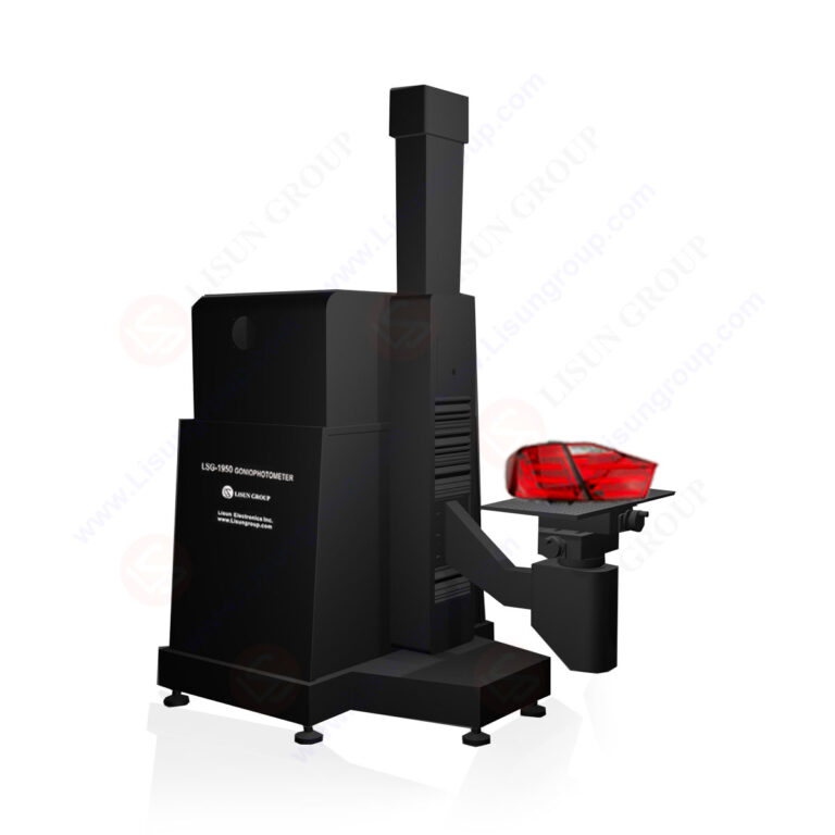
Image disclaimer: For identification and illustration only. It may show a product by another manufacturer and may not depict the exact item described; it is not a statement of any product’s quality, approval or performance. Third-party image and trademark rights belong to their owners. See full notice.
What Is It?
A Goniophotometer is a precision measurement system that combines a photometer (or spectroradiometer) with a mechanical rotation stage. It measures the luminous intensity of a light source as a function of angle (azimuth and elevation), producing a comprehensive spatial distribution map – the beam pattern. In AGL applications, every fixture has a defined beam pattern that must meet strict angular intensity requirements to ensure pilots receive adequate visual guidance from the correct angles.
Key beam pattern characteristics measured by a goniophotometer include:
- Beam width (spread) — the angular extent of the main beam (e.g., 4° vertical × 6° horizontal for centreline lights)
- Peak intensity direction (aiming point) — the angle at which the light is most intense
- Intensity uniformity — how smoothly the intensity varies across the beam
- Off‑axis performance — intensity at critical viewing angles (e.g., side‑lobe levels)
- Colour uniformity — chromaticity variation across the beam (when combined with a colorimeter/spectrometer)
Goniophotometers are primarily used in laboratory settings for type testing, certification, and R&D. They are essential tools for AGL manufacturers and accredited testing laboratories.
Purpose & Function
The goniophotometer's purpose is to verify not just how bright a fixture is, but whether that brightness is being delivered at exactly the angles a pilot will actually be looking from during approach, landing, and rollout — since a fixture with the right peak intensity but a beam that is too narrow, too wide, or aimed slightly off-axis can still fail to provide adequate guidance at the angles that matter operationally. By mapping intensity across the full range of azimuth and elevation angles, it produces the complete beam-pattern data that ICAO and FAA specifications require for certification, and it gives engineers the angular detail needed to diagnose problems — such as a misaligned reflector or an incorrect optical component — that a single-point intensity reading would miss entirely.
Where Is It Used?
Goniophotometers are deployed in specialised scenarios where full spatial intensity data is required:
- Type Testing and Certification: AGL fixtures must be tested in an accredited laboratory using a goniophotometer to verify compliance with ICAO Annex 14 and the relevant FAA L‑type fixture specification's beam pattern requirements (e.g. AC 150/5345‑46). The test results are used for certification and to generate photometric data sheets.
- Product Development and R&D: When designing new AGL fixtures (especially LED‑based designs), engineers use goniophotometers to optimise the optical system (reflectors, lenses, prisms) to achieve the required beam shape and intensity.
- Quality Assurance in Manufacturing: High‑end manufacturers may use goniophotometers to perform sample testing from each production batch to ensure consistent optical performance.
- Forensic Troubleshooting: When an AGL system exhibits unexpected performance issues (e.g., poor visibility from certain angles), a goniophotometer can be used to measure the actual beam pattern of a suspect fixture and compare it with the design specification, revealing misalignment, optical damage, or incorrect component sourcing.
- Calibration of Field Measurement Tools: Portable alignment tools and photometers used in the field can be calibrated using the accurate intensity and angle data from a reference goniophotometer.
Storage & Handling
As a large, precision optical instrument, the goniophotometer is a fixed installation within an accredited testing laboratory or manufacturer's QC facility rather than field-portable equipment, housed in a dark room isolated from vibration and stray light that would otherwise corrupt intensity measurements. The fixture-under-test is brought to the goniophotometer and mounted on its rotating stage, rather than the instrument being moved, and the room's environmental controls (temperature, humidity, blackout) are maintained continuously to protect both the instrument's optics and the validity of ongoing test series. Access is restricted to trained operators, and the unit undergoes its own periodic calibration against reference standards to keep its angular and intensity measurements traceable.
How Does It Work?
A typical goniophotometer system consists of the following components:
- Mechanical Rotation Stage: A precision motorised goniometer that rotates the fixture (or the photometer) around one or two axes. Common configurations include:
- Mirror‑type goniophotometer: The fixture remains fixed while a mirror rotates, directing the beam to a stationary photometer. This is suitable for heavy fixtures.
- Rotating arm goniophotometer: The fixture rotates around a vertical axis, and the photometer moves along a horizontal arc to cover elevation angles.
- Double‑axis goniophotometer: The fixture rotates around both azimuth and elevation axes, providing full spherical coverage.
- Photodetector (Photometer or Spectroradiometer): A calibrated light sensor that measures intensity at each angular position. The detector is placed at a fixed distance (typically 10 m, 30 m, or 100 m) from the fixture, following the inverse square law for intensity calculations.
- Control and Data Acquisition System: Software that synchronises the rotation, captures the detector signal, and records the intensity as a function of angles. The system also corrects for background light, detector dark current, and distance variations.
- Analysis Software: Post‑processing tools that generate polar plots, isocandela diagrams, and tabulated intensity values at specified angular increments. The software can compare the measured data against the required standard and produce pass/fail reports.
For AGL measurements, the fixture is powered at the required current step (e.g., 6.6 A for max intensity). The goniophotometer scans the beam in both horizontal (azimuth) and vertical (elevation) planes, typically in steps of 0.5° to 2°. The measured intensities are then used to calculate the beam pattern, which must fall within the tolerance zones defined in the relevant standard.
Angular scanning path from rotation stage to pass/fail verdict
Fixture Under Test
Powered by CCR at required current step (e.g., 6.6 A)
Mechanical Rotation Stage
Motorised goniometer sweeps azimuth/elevation in one of three configurations
Fixture fixed; rotating mirror redirects beam to a stationary detector — suited to heavy fixtures
Fixture rotates on vertical axis; detector arcs horizontally for elevation coverage
Fixture rotates on both azimuth and elevation axes for full spherical coverage
Photodetector at Fixed Distance
Measures intensity at each angular position (10 m / 30 m / 100 m, per inverse square law)
Control & Data Acquisition
Synchronises rotation with capture; corrects for ambient light, dark current, distance
Polar Plot vs. Standard Tolerance Zones
Isocandela diagram compared against required beam envelope — Pass / Fail
System Architecture & Control Logic
The goniophotometer's control architecture is a closed motion-and-measurement loop rather than a power-distribution one: a control computer commands the rotation stage to step through a sequence of azimuth and elevation angles, waits for the mechanism to settle at each position, and triggers the photodetector to take a reading before advancing to the next angle. Feedback in this loop comes from position encoders on the rotation stage, which confirm the actual angle reached matches the commanded angle before a measurement is logged, and from repeat or reference readings that catch drift in the fixture's output during a long scan. The fixture under test itself is usually powered from a separate, fixed-current supply set to the required CCR step rather than the goniophotometer's own control system, so the goniophotometer's logic governs only the measurement geometry and timing, while the resulting angle-by-angle intensity table is what downstream analysis software checks against the beam-pattern tolerance envelope in the applicable standard.
Physical Construction
The system is built around a precision motorised rotation stage — or a moving-mirror/goniometer arm in some designs — that sweeps a calibrated photometer or spectroradiometer detector through the full azimuth and elevation range around a fixed fixture-under-test, with mechanical positioning accurate to a fraction of a degree. The fixture holder is an adjustable clamp and mounting plate designed to accept AGL luminaires of different shapes and sizes, from small inset units to larger elevated fixtures, and includes an integrated CCR or variable supply so the fixture can be powered at its rated series-circuit current during the test. The whole assembly is installed in a darkened photometric laboratory or dark tunnel, walled and baffled with matte black, non-reflective surfaces to prevent stray light from reaching the detector, and held at a controlled temperature since lamp output and detector response both drift with ambient conditions. Data cabling runs from the detector and positioning stage back to a control computer over USB or Ethernet, where the intensity readings at each angle are logged and assembled into the fixture's photometric distribution.
Technical Parameters
| Parameter | Typical Value |
|---|---|
| Measurement Type | Far‑field luminous intensity distribution (candelas) |
| Angular Range (Azimuth) | 0° – 360° (full circle) |
| Angular Range (Elevation) | Typically -90° to +90° (or -180° to +180° depending on configuration) |
| Angular Resolution | 0.1° to 1° (adjustable) |
| Measurement Distance | Typically 10 m, 30 m, or 100 m |
| Detector Type | Photometer (V(λ) corrected) or Spectroradiometer |
| Intensity Range | 0.1 cd – 1,000,000 cd (depending on detector) |
| Accuracy (Intensity) | ±2% of reading (typical) |
| Positioning Accuracy | ±0.1° (mechanical) |
| Data Interface | USB, Ethernet, or proprietary software |
| Fixture Mounting | Adjustable fixture holder to accommodate various AGL fixture sizes (inset, elevated) |
| Power Supply | AC mains (230 V / 110 V) with integrated CCR for fixture power |
| Operating Environment | Dark room or photometric laboratory with controlled temperature (23°C ± 2°C) |
Electrical Requirements
| Requirement | Typical Value |
|---|---|
| Circuit Type | Mains-powered laboratory instrument, with an integrated CCR to power the fixture under test |
| Power Supply | AC mains, 230V / 110V |
| Fixture Power (Device Under Test) | Integrated CCR output matched to the AGL fixture's rated series current (e.g. 6.6A) |
| Cable Type | Data interface via USB/Ethernet; fixture power via L-823/L-824 style leads to the test fixture |
| Earthing/Grounding | Instrument frame and fixture holder bonded to the laboratory earth |
| Fault Protection | Mains-side overcurrent protection; CCR output protected per its own regulator design |
Applicable Standards
ICAO Annex 14
Beam pattern requirements for all AGL fixtures
FAA AC 150/5345‑46
Photometric test methods are embedded within each L‑type fixture spec, e.g. this one for runway/taxiway light fixtures
IEC 61827
Characteristics of inset and elevated aeronautical ground lights, incl. photometric requirements
CIE 121
Recommendations for the photometry and goniophotometry of luminaires
Setup Requirements
Reference Standard Lamp Warm-Up
Pre-UseWarm up and verify the reference standard lamp before starting a measurement session, since intensity readings depend on this reference being stable.
Fixture-Under-Test Mounting & Aiming
Pre-UseMount the fixture under test on the rotating stage and align it to the goniophotometer's reference axis before starting the scan.
Dark Room & Stray Light Check
Pre-UseConfirm the room is free of stray light and vibration sources that would corrupt intensity measurements before beginning.
Integrated Power Supply Verification
Pre-UseConfirm the fixture's power supply or CCR interface delivers the correct rated voltage/current before starting the scan.
Angular Range & Resolution Configuration
Pre-UseConfigure the scan's angular range and resolution to match the fixture type's applicable photometric standard before starting.
Testing & Commissioning
Reference Standard Lamp Calibration Check
CalibrationVerify the instrument's intensity and angular readings against a traceable reference standard lamp before it is used to commission or certify AGL fixtures.
Angular Positioning Accuracy Verification
CalibrationConfirm azimuth and elevation positioning against calibrated angular references, checking mechanical accuracy stays within the rated ±0.1° tolerance.
Detector Linearity & Spectral Response Check
CalibrationVerify the photometer or spectroradiometer detector's linearity across its intensity range and confirm its V(λ) photopic correction remains within specification.
Fixture Mounting & Aiming Alignment
VerificationConfirm the adjustable fixture holder locates the test fixture's optical centre and aiming reference correctly for the fixture type under test.
Integrated CCR / Power Supply Verification
VerificationConfirm the integrated constant current supply delivers the correct rated current to the fixture under test at each required intensity step.
Repeatability Test
VerificationRepeat a measurement on a known reference fixture and confirm results fall within the instrument's stated accuracy and repeatability claims.
Data Interface & Report Format Verification
AcceptanceConfirm data export via USB, Ethernet, or software produces a report in the format required for ICAO/FAA photometric compliance submissions.
Documentation & Calibration Certificate
AcceptanceRecord calibration readings, reference standard traceability, and measurement uncertainty budget, issuing a calibration certificate for handover.
Inspection & Maintenance
Alignment Verification
Before each test seriesConfirm fixturing and rotational axis alignment against a reference standard before beginning measurements.
Detector Calibration Check
AnnualVerify detector linearity and response across the full measurement range against a traceable reference.
Stray Light Baseline Check
Semi-annualRe-run a dark or ambient baseline measurement to confirm the test environment remains adequately light-controlled.
Thermal Stabilisation Check
Per test sessionConfirm the fixture warm-up procedure is followed before readings are taken to avoid thermally-skewed results.
Common Field Issues
Fixturing and Alignment Errors
Proper alignment of the fixture on the goniometer is critical. The fixture's optical axis must be precisely aligned with the rotation centre. Even small angular errors (0.1°) can shift the measured beam pattern significantly, causing false failures. Use laser alignment tools and precision datum points on the fixture.
Stray Light and Ambient Reflections
Goniophotometers are sensitive to stray light from the fixture's own reflections off walls, floor, or the rotation stage. The measurement room must be painted matte black, and baffles should be used to block direct reflections. Regular background subtraction and dark‑room measurements are essential.
Detector Non‑linearity and Saturation
Photodetectors can saturate when measuring high‑intensity beams (e.g., approach lights at 6.6 A). Using neutral density filters or adjusting the integration time helps. The detector's linearity must be verified using a set of calibrated neutral density filters.
Thermal Effects on Fixture Output
As the fixture heats up during measurement (especially halogen lamps), its intensity and beam pattern can change. Allow the fixture to stabilise at its normal operating temperature (typically 10–15 minutes) before starting the scan. For LEDs, the thermal equilibrium is usually faster but still should be monitored.
Data Interpretation and Standard Tolerances
Interpreting goniophotometric data requires careful comparison with the standard's tolerance zones. ICAO and FAA define minimum intensities at specific angles and also impose limits on intensity gradients. Software tools that automatically check against these criteria are indispensable.
Troubleshooting Guide
Measured Beam Pattern Doesn't Match Expected Shape
Elevated Background / Noisy Baseline Readings
Readings Flatten Out at High Intensity
Intensity Readings Change Over the Course of a Scan
Result Fails Standard Tolerance Check Unexpectedly
Failure Modes & Root Causes
Optical Axis Misalignment
Stray Light Contamination
Detector Saturation
Thermal Drift of the Fixture Under Test
Rig Mechanical Wear
Safety & Operational Notes
Isolate the Fixture Under Test When Not Measuring
Electrical SafetyDe-energise the fixture under test between measurement runs and when adjusting mounting or alignment hardware, since fixtures on the rig are often powered from mains or CCR-equivalent supplies.
Mechanical Pinch Points on the Rotation Stage
Personnel SafetyKeep hands and loose clothing clear of the rotation stage while it is moving, and confirm the stage is stopped and, where possible, locked out before reaching into the test volume.
Eye Protection Near Bright Sources
Personnel SafetyAvoid looking directly into the beam of high-intensity fixtures under test, particularly at close range or on-axis, and use appropriate eye protection where the light source warrants it.
Allow Fixture Cool-Down
Personnel SafetyAllow the fixture under test to cool before handling it for repositioning, since sustained operation during a measurement sequence can heat the housing and lens significantly.
Verify Rig Calibration and Alignment
ComplianceCheck optical axis alignment and detector calibration against a reference source before a measurement campaign, since even small axis or wear-related drift can invalidate the beam-pattern result.
Confirm Results Before Sign-off
ComplianceCompare the measured beam pattern against the applicable photometric standard before issuing a pass/fail result, and flag any reading that falls near the tolerance boundary for a repeat measurement.
Engineering & Expert Notes
Mechanical Axis Alignment Errors Compound Across the Whole Beam Map
CalibrationA goniophotometer's rotation stage axes must be aligned to the photometric bench's reference axis with real precision; a small consistent offset doesn't just shift one reading, it subtly distorts the entire beam pattern map in a way that can be hard to spot without comparing against a known reference fixture. Verify axis alignment against a certified reference source, not just the mechanical calibration of the stage itself.
Angular Resolution Trades Off Against Test Time — Choose It Deliberately
TestingA coarse angular step size finishes a scan quickly but can miss a narrow dip or peak in the beam pattern that falls between sampled points, particularly near a sharp transition edge on PAPI-type optics. Match the angular resolution to how tightly collimated the fixture under test actually is, rather than using one default resolution for every fixture type.
Allow the Fixture Under Test to Fully Stabilise Before Scanning
Field TechniqueBoth LED and traditional lamp sources shift output somewhat as they warm from a cold start, and beginning a full angular scan before the source has stabilised produces a beam map that's internally inconsistent, since early-scanned angles were measured at a different output level than later ones. Confirm output stability before starting the scan, not just before taking a single reading.
Mounting Repeatability Matters as Much as Mounting Accuracy
TestingIf a fixture is remounted partway through a test series, for example after a modification, slight differences in how it sits in the fixture even within nominal tolerance can shift the beam pattern enough to confuse a before/after comparison. Use a repeatable mounting jig and note any remounting between scans that are meant to be directly compared.
Stray Light Control Is a Whole-Room Discipline, Not Just a Baffle Around the Detector
EnvironmentalReflections off walls, ceiling, or equipment in the test chamber can contribute enough stray light to skew low-intensity off-axis readings, even with proper baffling immediately around the detector head. Periodically verify the chamber's stray-light floor with the source off, not just when initially commissioning the facility.
Cross-Check a Sample of Lab Results Against Field Photometer Readings
VerificationA goniophotometer characterises a fixture in controlled lab conditions, but the field photometer is what actually verifies installed performance; periodically correlating results from the two on the same fixture batch confirms the lab data is still a reliable predictor of what gets measured once fixtures are in service.
Frequently Asked Questions
Short answers about the goniophotometer: what it is, how it works, specifications, standards, maintenance and common faults.
Q1What is a goniophotometer?
A goniophotometer is a precision measurement system that combines a photometer or spectroradiometer with a mechanical rotation stage. It measures the luminous intensity of a light source as a function of angle, azimuth and elevation, producing a full spatial distribution map of the beam pattern.
Q2Why do AGL fixtures need goniophotometer testing?
Each fixture has a defined beam pattern that must meet strict angular intensity requirements so pilots receive adequate visual guidance from the correct angles. Goniophotometry verifies that, and produces the results used for certification and photometric data sheets.
Q3What does a goniophotometer measure?
Beam width (for example 4° vertical by 6° horizontal for centreline lights), peak intensity direction (aiming point), intensity uniformity across the beam and off-axis performance.
Q4What types of goniophotometer are there?
A mirror type keeps the fixture fixed while a mirror directs the beam to a stationary photometer, which suits heavy fixtures. A rotating arm type rotates the fixture about a vertical axis while the photometer moves along an arc. A double-axis type rotates the fixture in both azimuth and elevation for full spherical coverage.
Q5Where are goniophotometers used?
In specialised scenarios needing full spatial intensity data: type testing and certification in accredited laboratories against ICAO Annex 14 and the relevant FAA L-type fixture specification (for example AC 150/5345-46), and product development.
Q6What are the typical specifications?
Azimuth 0° to 360°, elevation typically -90° to +90°, angular resolution 0.1° to 1°, and positioning accuracy ±0.1°. Measurement distance is typically 10 m, 30 m or 100 m, the intensity range about 0.1 cd to 1,000,000 cd and intensity accuracy typically ±2% of reading.
Q7How is the fixture under test powered?
The instrument is mains-powered (230 V or 110 V) with an integrated CCR matched to the fixture's rated series current, for example 6.6 A. It is a laboratory instrument and not part of an airfield series circuit.
Q8Which standards apply?
The main references are ICAO Annex 14, FAA AC 150/5345-46 (photometric test methods within each L-type fixture specification), IEC 61827 and CIE 121 (photometry and goniophotometry of luminaires). Always verify the current edition and your accreditation requirements.
Q9How is a goniophotometer maintained?
Typical intervals are before each test series for alignment verification, per test session for thermal stabilisation, semi-annual for a stray light baseline check and annual for detector calibration. Your laboratory's quality procedures take precedence.
Q10What are the common problems with goniophotometer measurements?
Common problems are optical axis misalignment, stray light and ambient reflections, detector non-linearity and saturation, thermal drift of the fixture under test and rig mechanical wear. A measured beam pattern that does not match the expected shape, or readings that flatten at high intensity, point to these causes.
Related Components
Go Beyond the Component. Understand the Complete AGL System.
You have explored the component. Now understand how it works within the complete Airfield Ground Lighting system.
Learn AGL from fundamentals to design, installation, testing, photometry, commissioning, maintenance and troubleshooting through structured technical training at Precision AGL Academy.
Build practical knowledge. Understand the circuit. Read the standards. Troubleshoot with confidence.
Your next step in AGL starts here.
Need expert guidance on goniophotometric testing or equipment selection?
Precision AGL Academy provides advice on measurement protocols, fixture alignment, and interpretation of beam pattern data for AGL certification.
Follow the Academy
Important Notice, Disclaimer & Limitation of Liability
Please read before relying on any content on this page.
- Purpose and intended users. This page on Goniophotometer is an independent educational and informational reference for competent, suitably trained and authorised airfield ground lighting (AGL) and aerodrome electrical personnel. It is not professional engineering, legal or regulatory advice, and using it does not create any professional or client relationship.
- Safety. Work on series circuits, constant current regulators (CCRs), isolating transformers, cables, connectors and lighting equipment can be fatal. Always apply the aerodrome’s permit-to-work and isolation/LOTO procedures, prove dead, use correctly rated instruments and PPE, and follow the manufacturer’s instructions. Nothing here authorises work on live equipment or the bypassing of any safety device or interlock.
- Aviation operations. Nothing here authorises installation, modification, energisation, adjustment, return to service, a change of operating category (CAT I/II/III), a NOTAM or any aerodrome certification or approval decision. These rest with the aerodrome operator, the air navigation service provider and the competent regulator.
- Specifications, ratings and typical values. Descriptions, parameters, ratings, dimensions, photometric values, wattages, service lives, maintenance tasks and intervals, failure modes, certifications (for example CE, FCC, UL or IEC marks) and part or type designations are general, typical and indicative. They may not match any particular product, make, model or version, and they are not a datasheet, design, specification, selection, sizing, procurement or acceptance criterion. The manufacturer’s current documents, the approved design and the project specification prevail.
- Standards and regulations. References to ICAO, FAA, IEC, IEEE, ISO, BIS, DGCA and other standards are paraphrased summaries for orientation only. They may be incomplete or out of date, and standards are revised from time to time. Consult the current official editions. Following this content does not guarantee compliance with any law, standard or regulatory approval, and the regulator’s requirements always prevail.
- No warranty. Content is provided “as is” and “as available”, without warranty of any kind, express or implied, including accuracy, completeness, currency or fitness for a particular purpose. Real installations differ in design, equipment make and model, age and condition.
- Limitation of liability. To the fullest extent permitted by applicable law, Precision AGL Academy, Precision AGL Solutions and their owners, authors and contributors are not liable for any injury, death, loss, damage, downtime, penalty or regulatory consequence, whether direct or indirect, arising from the use of, reliance on, or inability to use this content. Nothing in this notice excludes or limits any liability that cannot lawfully be excluded or limited.
- Independence, brands and no endorsement. This is an independent publication. It is not affiliated with, sponsored by or endorsed by ICAO, the FAA, the IEC, DGCA, AAI, any airport, regulator, supplier or equipment manufacturer. Third-party names, product designations, standard designations and trademarks (including Megger®, Siemens, Eaton, Crouse-Hinds, ADB SAFEGATE, Fluke, ABB and Honeywell) belong to their respective owners and are used only for identification and description. Mention of a brand, product or supplier is not a recommendation, and we do not sell, supply or quote for any component described.
- Images and third-party content. Images and illustrations are shown to help identify the type of component. They may show products of various manufacturers, may not depict the exact item described, and are not a statement about any product’s quality, approval or performance. Copyright and trademarks in third-party images, logos and photographs belong to their respective owners and are not claimed as ours. If you are a rights holder and want an image removed, replaced or credited, email precisionaglsolutions@gmail.com with the page address and we will act promptly.
- Training and services. Mentions of training, courses, consultation, advice, selection, installation, calibration or other support, including the “Learn…Certify” pathway, describe learning stages and are not an offer, quotation, tender or promise of any result. Contacting us or our replying creates no engagement or duty of care; an engagement exists only under a written agreement. We are not a regulator or certification body, and completing any course or reading this content is not a certification, accreditation or authorisation to work on any aerodrome.
- Copyright, privacy and corrections. © 2026 Precision AGL Academy. All rights reserved. Text, structure, compilations and diagrams may be viewed for personal reference and internal training only; any other copying, republication or commercial use needs our written permission. If you email, telephone or message us, we use your details only to respond and handle your matter, in line with applicable Indian law including the Digital Personal Data Protection Act, 2023; please do not send confidential or security-sensitive information. To display this page your browser requests fonts, icons and images from third-party servers, which receive your IP address and browser details under their own policies. Content is reviewed periodically with no obligation to update. To report an error, safety concern or rights issue, write to precisionaglsolutions@gmail.com.