Colorimeter
A precision optical instrument used to measure the chromaticity (colour coordinates) of AGL light sources. Ensures that runway, taxiway, and approach lights conform to the strict colour specifications defined by ICAO, FAA, and IEC, which are critical for correct visual signalling and pilot interpretation.
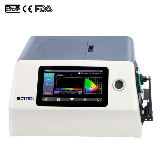
Image disclaimer: For identification and illustration only. It may show a product by another manufacturer and may not depict the exact item described; it is not a statement of any product’s quality, approval or performance. Third-party image and trademark rights belong to their owners. See full notice.
What Is It?
A Colorimeter is an optoelectronic instrument that quantifies the colour of light emitted by an AGL fixture. Unlike a photometer, which measures intensity, a colorimeter focuses on chromaticity — the subjective colour perceived by the human eye, expressed in standard CIE (International Commission on Illumination) coordinates. In airfield lighting, each colour (aviation red, green, yellow, blue, white) has a defined chromaticity boundary within the CIE 1931 (x,y) or 1976 (u',v') colour spaces. The colorimeter verifies that the fixture's output falls within the required tolerance box, ensuring unambiguous visual signals for pilots.
Key colour standards for AGL include:
- Aviation Red: Used for runway end lights, obstruction lights, and stop bars.
- Aviation Green: Used for threshold lights, taxiway centreline lights, and lead‑on lights.
- Aviation Yellow: Used for intermediate holding position lights and clearance bars.
- Aviation Blue: Used for taxiway edge lights.
- Aviation White: Used for runway edge, centreline, and approach lights.
Purpose & Function
The colorimeter's purpose is to confirm that a fixture's colour is not just close to the right shade of red, green, yellow, blue, or white, but falls inside the precise chromaticity boundary that gives that colour its specific operational meaning to a pilot. Because a pilot's decisions — whether they are looking at a threshold, a runway end, or a taxiway edge — depend on correctly identifying colour at a glance, a fixture whose colour has drifted outside its tolerance box, even if it still looks broadly correct to the eye, can create genuine ambiguity about what the light is signalling. The colorimeter's function is to catch that drift objectively, whether during manufacturing quality control, type certification, or a routine field check prompted by a pilot report of an off-colour light.
Where Is It Used?
Colorimeters are deployed in various stages of the AGL lifecycle to ensure colour compliance:
- Manufacturing Quality Control: Used by AGL fixture manufacturers to verify that each production batch meets the specified chromaticity requirements before shipping.
- Type Testing and Certification: Independent testing laboratories use colorimeters to certify that new fixture models comply with ICAO, FAA, and IEC colour standards.
- Airport Commissioning: During new AGL system installation, colorimeters are used to confirm that every fixture emits the correct colour when powered at the required current steps.
- Periodic Maintenance Inspection: Airports perform regular colour checks (e.g., annually) to detect colour shifts due to ageing of filters, LEDs, or optical components.
- Troubleshooting: When pilots report colour confusion (e.g., a green light appearing yellowish), a colorimeter is used to pinpoint the cause — often a degraded filter or incorrect LED bin.
- Calibration of Field Test Equipment: Simpler colour‑checking devices (e.g., colour filters) are calibrated against a reference colorimeter.
Storage & Handling
The colorimeter is stored in its padded carry case between uses, with the sensor head or optical port protected by a lens cap to keep dust and fingerprints off the measurement surface. It is kept in a stable, moderate-temperature environment when not in use and allowed to acclimatise before taking readings if moved between significantly different temperatures, since thermal drift can affect sensor accuracy. Field crews carry it out to the fixture being tested rather than removing the fixture, and the unit is periodically checked against a reference calibration standard to confirm its readings remain within tolerance, with the calibration due date tracked alongside the instrument's storage record.
How Does It Work?
A colorimeter typically uses one of the following methods to measure colour:
- Tristimulus Filter Method: The instrument uses three or more photodetectors, each fitted with a filter that mimics the CIE colour‑matching functions (x̄, ȳ, z̄). By measuring the response through each filter, the instrument calculates the tristimulus values (X, Y, Z) and derives the chromaticity coordinates (x, y). This is the most common approach for field instruments due to its simplicity and speed.
- Spectroradiometric Method: A more advanced technique where the instrument measures the full spectral power distribution (SPD) of the light source using a diffraction grating and a linear array detector. From the SPD, the CIE coordinates are computed with high accuracy. This method is used in reference laboratories and for type testing.
For AGL measurements, the colorimeter is positioned at a specific distance and angle relative to the fixture (often the same geometry as intensity measurements). The fixture is operated at the required current step, and the colorimeter records the chromaticity coordinates. The results are compared against the relevant standard’s colour boundary table to determine pass/fail.
Two measurement paths converging on the same chromaticity check
Fixture Under Test
Operated at required current step, at defined distance and angle
Three+ filtered photodetectors mimic CIE colour-matching functions (x̄, ȳ, z̄)
Tristimulus values X, Y, Z calculated from filter response — fast, common in field instruments
Diffraction grating + linear array detector capture full spectral power distribution
CIE coordinates computed from SPD — higher accuracy, used in reference labs
Chromaticity Coordinates (x, y)
Compared against the standard's colour boundary table — Pass / Fail
System Architecture & Control Logic
The colorimeter operates as a standalone measurement instrument rather than a controlled system component, but it sits within a broader photometric verification architecture. It is typically synchronised with the fixture's power supply (set to the specific current step being tested) and, in a test-bench or production line setup, its digital output feeds into the same data acquisition and pass/fail reporting software used for intensity measurements, so a single test run can log both luminous intensity and chromaticity coordinates against the fixture's serial number. There is no feedback loop in the electrical sense — the colorimeter does not adjust the fixture it is measuring — but the pass/fail verdict it produces is what gates whether that fixture proceeds to shipment, installation, or return for rework, making it a control point in the quality process even though it exerts no control over the electrical circuit itself.
Physical Construction
The colorimeter is built around a precision measurement head containing either filtered tristimulus photodetectors or a miniature spectrograph, mounted behind an optical aperture that defines the instrument's field of view and fixes its viewing distance and angle relative to the fixture's optical axis. The head and body are housed in a rigid polymer or metal shell that maintains consistent internal baffling to exclude stray light, with the aperture ring precisely machined to hold that fixed, repeatable measurement geometry against the light source under test. Data interface ports (USB, Bluetooth, or RS-232) and the power/battery compartment are positioned away from the optical path to avoid contaminating readings, and the housing carries an IP54-rated seal around seams and connector covers for field use in outdoor AGL environments. A protective lens cap or calibration tile holder is typically supplied to shield the optics and provide an on-site reference check between formal calibrations.
Technical Parameters
| Parameter | Typical Value |
|---|---|
| Measurement Principle | Tristimulus (filter) or Spectroradiometric |
| Chromaticity Accuracy | ±0.002 (x,y) for tristimulus; ±0.0005 for spectroradiometric |
| Wavelength Range | 380 nm – 780 nm (visible spectrum) |
| Colour Spaces Supported | CIE 1931 (x,y), CIE 1976 (u',v'), correlated colour temperature (CCT) |
| Measurement Geometry | Fixed viewing distance and angle on the fixture's optical axis (not reflectance geometry — the fixture is a self-luminous source, not a reflecting sample) |
| Field of View | Typically 1° to 2° for directional measurements |
| Data Interface | USB, Bluetooth, RS-232, or Wi-Fi |
| Power Supply | Internal rechargeable battery or AC adapter |
| Operating Temperature | -10°C to +50°C (field use) |
| Protection Class | IP54 (for field instruments) |
Electrical Requirements
| Requirement | Typical Value |
|---|---|
| Power Supply | Internal rechargeable battery or AC adapter |
| Charging Input | USB or dedicated AC charger per manufacturer rating |
| Sensor Head Power | Low-voltage supply to the optical detector/tristimulus filter array |
| Data Interface Power | Low-voltage supply for USB/Bluetooth/Wi-Fi communication module |
| Earthing/Grounding | No installed earth required for battery-powered field use; AC adapter earthed per local wiring rules when used |
Applicable Standards
ICAO Annex 14
Colour specifications for all AGL lights (red, green, yellow, blue, white)
FAA AC 150/5345‑46
Specification for Runway, Taxiway, Heliport, and Vertiport Light Fixtures (includes chromaticity requirements)
IEC TS 61827
Characteristics of inset and elevated AGL luminaires (colour/photometric reference)
CIE (International Commission on Illumination)
Colour spaces and measurement procedures (CIE 15, CIE S014)
Testing & Commissioning
Calibration Certificate Verification
AcceptanceConfirm the colorimeter's calibration certificate is current before it is used for photometric colour acceptance testing.
White/Reference Tile Check
AcceptanceMeasure the supplied reference tile or calibration source and confirm the reading matches its certified chromaticity value.
Chromaticity Verification Against Known Standard
AcceptanceCross-check a known-colour light source against the instrument's reading to confirm chromaticity accuracy remains within specification.
Aperture/Geometry Check
AcceptanceInspect the measurement aperture and contact tip for damage or contamination that could bias the measurement geometry.
Documentation & Sign-off
AcceptanceLog the reference tile check and calibration due date against the instrument's serial number.
Inspection & Maintenance
Recalibration Against Reference Lamp
AnnualSend the colorimeter for recalibration against a traceable reference lamp to correct for optical filter ageing.
Field Check with Colour Standard
Before each sessionVerify readings against a stable LED reference standard before each measurement campaign to catch drift between calibrations.
Optical Filter & Window Cleaning
QuarterlyClean optical filters and windows to prevent humidity, dust, or UV residue from shifting the spectral response.
Temperature Stabilisation Verification
QuarterlyAllow both the fixture under test and the colorimeter to reach normal operating temperature before taking readings.
Alignment & Viewing Angle Check
Semi-annualVerify the sighting system or goniometric setup is correctly aligned to the specified measurement angle.
Common Field Issues
Filter Ageing and Calibration Drift
Tristimulus colorimeters rely on precision optical filters that can degrade over time due to humidity, temperature, and UV exposure. This shifts the spectral response, leading to colour measurement errors. Annual recalibration against a traceable reference lamp is essential. Field checks with a calibrated colour standard (e.g., a stable LED reference) are recommended before each measurement campaign.
Ambient Light Contamination
Outdoor measurements are susceptible to sunlight and other ambient light sources, which can skew chromaticity readings. Using a baffle tube, measuring at night, or employing a modulation/demodulation technique (lock‑in) helps minimise interference. Some instruments have a built‑in ambient light subtraction feature.
Temperature Sensitivity
Both LEDs and photodetectors change their spectral output with temperature. For accurate colour measurements, the fixture should be operated at its normal operating temperature (allow warm‑up time). The colorimeter itself should be stabilised to ambient temperature before use.
Beam Alignment and Viewing Angle
Colour may vary with viewing angle for some fixtures (especially LEDs). The measurement must be taken at the specified angle (usually the beam centre) as defined in the standard. Misalignment can result in erroneous colour readings. Using a precise sighting system or a goniometric setup is recommended.
Troubleshooting Guide
Chromaticity Reading Falls Outside the Expected Colour Box
Reading Varies Significantly With Ambient Conditions
Reading Drifts Over an Extended Test Session
Reading Changes Significantly With Viewing Angle
Instrument Fails to Calibrate Against Its Reference Standard
Failure Modes & Root Causes
Tristimulus Filter Ageing / Drift
Ambient Light Contamination
Thermal Instability During a Session
Incorrect Measurement Angle
Reference Standard or Optics Fault
Safety & Operational Notes
Avoid Looking Directly Into the Light Source
Personnel SafetyPosition the colorimeter's sensor head to capture the fixture's output rather than placing your eye at the beam axis, particularly for high-intensity fixtures, to avoid discomfort or glare-induced flash blindness.
Airside Work Coordination
OperationalAny test carried out on an active runway or taxiway fixture requires ATC/airside coordination and a NOTAM where the fixture will be dark, dimmed, or partially obstructed during the reading, with vehicle and personnel movement kept clear of the strip per the aerodrome's safety management procedures.
Instrument Calibration Currency
ComplianceConfirm the colorimeter's calibration certificate is current and traceable before relying on its readings for compliance testing, since chromaticity acceptance is judged against tight CIE coordinate boundaries.
Allow Fixture and Instrument to Stabilise
OperationalAllow a newly energised fixture (and the colorimeter itself, if recently moved between temperature extremes) to reach thermal stability before taking a reading, since output chromaticity can drift slightly during warm-up.
Correct Measurement Distance and Angle
OperationalPosition the sensor at the manufacturer's specified distance and angle relative to the fixture's beam axis; an off-axis or too-close reading can misrepresent the colour the fixture actually presents to an approaching pilot.
FOD Control at the Fixture
OperationalKeep tools, tripods, and test equipment accounted for at all times when working around an in-pavement or elevated fixture, and clear the area before reopening it to traffic.
PPE & Ground Awareness
Personnel SafetyWear high-visibility clothing for airside work and stay aware of surrounding vehicle and aircraft movement while attention is focused on the instrument display.
Record Results Against Compliance Boundary
ComplianceLog the measured chromaticity coordinates against the applicable CIE boundary for that fixture's designated colour, and flag any reading outside tolerance for follow-up before closing out the test.
Engineering & Expert Notes
Let LED Fixtures Thermally Stabilise Before Reading Chromaticity
TechniqueLED chromaticity shifts measurably as the die heats up from cold-start to steady-state operation; a colorimeter reading taken in the first minute after power-on can show a fixture passing or failing purely due to warm-up drift rather than its actual settled colour. Always let the fixture reach thermal equilibrium before recording a compliance reading.
Measurement Distance and Angle Affect Chromaticity Readings
TechniqueOff-axis colour shift is a real phenomenon on many AGL fixture designs; taking a colorimeter reading at an angle or distance that doesn't match the standard's specified measurement geometry can produce a chromaticity coordinate that doesn't reflect what a pilot actually sees on the intended approach or runway sightline.
A Reading Near the Boundary Deserves a Second Measurement
VerificationA chromaticity coordinate that falls just inside or just outside the required tolerance box is more informative as a trend than a single pass/fail; take a repeat reading before either failing a fixture that's marginally in spec or passing one that's marginally out, since instrument and environmental noise are largest right at the boundary.
Stray Ambient Light Skews Low-Level Readings
Field PracticeDaylight or nearby fixture spill can bias a colorimeter's reading on lower-intensity steps more than it does at full brightness; where possible, take critical chromaticity measurements at night or with the sensor properly shielded from ambient sources rather than in full daylight.
Sensor Calibration Drift Is Invisible Without a Reference Check
CalibrationA colorimeter's optical sensor can drift out of calibration gradually with no obvious symptom on the display; verify against a known reference source at the start of a measurement session rather than trusting the last calibration date alone, especially after the instrument has seen rough field handling.
Lens Contamination Shifts Colour Readings, Not Just Intensity
MaintenanceA dirty or UV-yellowed fixture lens doesn't just reduce measured intensity — it can shift the apparent chromaticity coordinate too, especially toward the yellow end of the spectrum; when a fixture reads marginal on colour, check and clean the lens before concluding the LED source itself has drifted out of tolerance.
Frequently Asked Questions
Short answers about the Colorimeter: what it is, how it works, typical specifications, standards, maintenance and common faults.
Q1What is a Colorimeter?
A Colorimeter is an optoelectronic instrument that quantifies the colour of light emitted by an AGL fixture. Unlike a photometer, which measures intensity, a colorimeter focuses on chromaticity — the subjective colour perceived by the human eye, expressed in standard CIE (International Commission on Illumination) coordinates. In airfield lighting, each colour (aviation red, green, yellow, blue, white) has a defined chromaticity boundary within the CIE 1931 (x,y) or 1976 (u',v') colour spaces.
Q2What is the purpose of a Colorimeter?
The colorimeter's purpose is to confirm that a fixture's colour is not just close to the right shade of red, green, yellow, blue, or white, but falls inside the precise chromaticity boundary that gives that colour its specific operational meaning to a pilot.
Q3Where is a Colorimeter used?
Colorimeters are deployed in various stages of the AGL lifecycle to ensure colour compliance: Manufacturing Quality Control: Used by AGL fixture manufacturers to verify that each production batch meets the specified chromaticity requirements before shipping. Type Testing and Certification: Independent testing laboratories use colorimeters to certify that new fixture models comply with ICAO, FAA, and IEC colour standards. Airport Commissioning: During new AGL system installation, colorimeters are used to confirm that every fixture emits the correct colour when powered at the required current steps.
Q4How does a Colorimeter work?
A colorimeter typically uses one of the following methods to measure colour: Tristimulus Filter Method: The instrument uses three or more photodetectors, each fitted with a filter that mimics the CIE colour‑matching functions (x̄, ȳ, z̄). By measuring the response through each filter, the instrument calculates the tristimulus values (X, Y, Z) and derives the chromaticity coordinates (x, y). This is the most common approach for field instruments due to its simplicity and speed.
Q5How should a Colorimeter be stored and handled?
The colorimeter is stored in its padded carry case between uses, with the sensor head or optical port protected by a lens cap to keep dust and fingerprints off the measurement surface. It is kept in a stable, moderate-temperature environment when not in use and allowed to acclimatise before taking readings if moved between significantly different temperatures, since thermal drift can affect sensor accuracy.
Q6What are the typical technical parameters of a Colorimeter?
Typical values are — Measurement Principle: Tristimulus (filter) or Spectroradiometric; Chromaticity Accuracy: ±0.002 (x,y) for tristimulus; ±0.0005 for spectroradiometric; Wavelength Range: 380 nm – 780 nm (visible spectrum); Colour Spaces Supported: CIE 1931 (x,y), CIE 1976 (u',v'), correlated colour temperature (CCT); Measurement Geometry: Fixed viewing distance and angle on the fixture's optical axis (not reflectance geometry — the fixture is a self-luminous source, not a reflecting sample); Field of View: Typically 1° to 2° for directional measurements; Data Interface: USB, Bluetooth, RS-232, or Wi-Fi.
Q7What are the electrical requirements for a Colorimeter?
Typical requirements are — Power Supply: Internal rechargeable battery or AC adapter; Charging Input: USB or dedicated AC charger per manufacturer rating; Sensor Head Power: Low-voltage supply to the optical detector/tristimulus filter array; Data Interface Power: Low-voltage supply for USB/Bluetooth/Wi-Fi communication module; Earthing/Grounding: No installed earth required for battery-powered field use; AC adapter earthed per local wiring rules when used.
Q8Which standards apply to a Colorimeter?
The main references are ICAO Annex 14 — Colour specifications for all AGL lights (red, green, yellow, blue, white); FAA AC 150/5345‑46 — Specification for Runway, Taxiway, Heliport, and Vertiport Light Fixtures (includes chromaticity requirements); IEC TS 61827 — Characteristics of inset and elevated AGL luminaires (colour/photometric reference); CIE (International Commission on Illumination) — Colour spaces and measurement procedures (CIE 15, CIE S014). Always verify the current edition and your aerodrome's approved requirements.
Q9How often should a Colorimeter be inspected and maintained?
Typical maintenance tasks and intervals are: Recalibration Against Reference Lamp (annual); Field Check with Colour Standard (before each session); Optical Filter & Window Cleaning (quarterly); Temperature Stabilisation Verification (quarterly); Alignment & Viewing Angle Check (semi-annual). Your airport's approved maintenance programme takes precedence.
Q10How do I troubleshoot common Colorimeter faults?
Common symptoms covered are: Chromaticity Reading Falls Outside the Expected Colour Box; Reading Varies Significantly With Ambient Conditions; Reading Drifts Over an Extended Test Session; Reading Changes Significantly With Viewing Angle; Instrument Fails to Calibrate Against Its Reference Standard. For example, for "Chromaticity Reading Falls Outside the Expected Colour Box": Likely Cause: Filter ageing/drift in the tristimulus sensor, a genuine shift in the fixture's LED output, or the reading was taken before the fixture reached thermal stability. Diagnostic Steps: Verify the colorimeter against a stable, traceable colour reference before condemning the fixture; allow the fixture adequate warm-up time; check the colorimeter's last recalibration date. Corrective Action: Recalibrate the colorimeter against a traceable reference if it fails the check, or replace the fixture's LED module if a genuine, repeatable colour shift is confirmed after full warm-up.
Related Components
Go Beyond the Component. Understand the Complete AGL System.
You have explored the component. Now understand how it works within the complete Airfield Ground Lighting system.
Learn AGL from fundamentals to design, installation, testing, photometry, commissioning, maintenance and troubleshooting through structured technical training at Precision AGL Academy.
Build practical knowledge. Understand the circuit. Read the standards. Troubleshoot with confidence.
Your next step in AGL starts here.
Need expert guidance on colour measurement or colorimeter selection?
Precision AGL Academy provides advice on colorimeter calibration, measurement protocols, and interpretation of chromaticity data for AGL colour compliance.
Follow the Academy
Important Notice, Disclaimer & Limitation of Liability
Please read before relying on any content on this page.
- Purpose and intended users. This page on Colorimeter is an independent educational and informational reference for competent, suitably trained and authorised airfield ground lighting (AGL) and aerodrome electrical personnel. It is not professional engineering, legal or regulatory advice, and using it does not create any professional or client relationship.
- Safety. Work on series circuits, constant current regulators (CCRs), isolating transformers, cables, connectors and lighting equipment can be fatal. Always apply the aerodrome’s permit-to-work and isolation/LOTO procedures, prove dead, use correctly rated instruments and PPE, and follow the manufacturer’s instructions. Nothing here authorises work on live equipment or the bypassing of any safety device or interlock.
- Aviation operations. Nothing here authorises installation, modification, energisation, adjustment, return to service, a change of operating category (CAT I/II/III), a NOTAM or any aerodrome certification or approval decision. These rest with the aerodrome operator, the air navigation service provider and the competent regulator.
- Specifications, ratings and typical values. Descriptions, parameters, ratings, dimensions, photometric values, wattages, service lives, maintenance tasks and intervals, failure modes, certifications (for example CE, FCC, UL or IEC marks) and part or type designations are general, typical and indicative. They may not match any particular product, make, model or version, and they are not a datasheet, design, specification, selection, sizing, procurement or acceptance criterion. The manufacturer’s current documents, the approved design and the project specification prevail.
- Standards and regulations. References to ICAO, FAA, IEC, IEEE, ISO, BIS, DGCA and other standards are paraphrased summaries for orientation only. They may be incomplete or out of date, and standards are revised from time to time. Consult the current official editions. Following this content does not guarantee compliance with any law, standard or regulatory approval, and the regulator’s requirements always prevail.
- No warranty. Content is provided “as is” and “as available”, without warranty of any kind, express or implied, including accuracy, completeness, currency or fitness for a particular purpose. Real installations differ in design, equipment make and model, age and condition.
- Limitation of liability. To the fullest extent permitted by applicable law, Precision AGL Academy, Precision AGL Solutions and their owners, authors and contributors are not liable for any injury, death, loss, damage, downtime, penalty or regulatory consequence, whether direct or indirect, arising from the use of, reliance on, or inability to use this content. Nothing in this notice excludes or limits any liability that cannot lawfully be excluded or limited.
- Independence, brands and no endorsement. This is an independent publication. It is not affiliated with, sponsored by or endorsed by ICAO, the FAA, the IEC, DGCA, AAI, any airport, regulator, supplier or equipment manufacturer. Third-party names, product designations, standard designations and trademarks (including Megger®, Siemens, Eaton, Crouse-Hinds, ADB SAFEGATE, Fluke, ABB and Honeywell) belong to their respective owners and are used only for identification and description. Mention of a brand, product or supplier is not a recommendation, and we do not sell, supply or quote for any component described.
- Images and third-party content. Images and illustrations are shown to help identify the type of component. They may show products of various manufacturers, may not depict the exact item described, and are not a statement about any product’s quality, approval or performance. Copyright and trademarks in third-party images, logos and photographs belong to their respective owners and are not claimed as ours. If you are a rights holder and want an image removed, replaced or credited, email precisionaglsolutions@gmail.com with the page address and we will act promptly.
- Training and services. Mentions of training, courses, consultation, advice, selection, installation, calibration or other support, including the “Learn…Certify” pathway, describe learning stages and are not an offer, quotation, tender or promise of any result. Contacting us or our replying creates no engagement or duty of care; an engagement exists only under a written agreement. We are not a regulator or certification body, and completing any course or reading this content is not a certification, accreditation or authorisation to work on any aerodrome.
- Copyright, privacy and corrections. © 2026 Precision AGL Academy. All rights reserved. Text, structure, compilations and diagrams may be viewed for personal reference and internal training only; any other copying, republication or commercial use needs our written permission. If you email, telephone or message us, we use your details only to respond and handle your matter, in line with applicable Indian law including the Digital Personal Data Protection Act, 2023; please do not send confidential or security-sensitive information. To display this page your browser requests fonts, icons and images from third-party servers, which receive your IP address and browser details under their own policies. Content is reviewed periodically with no obligation to update. To report an error, safety concern or rights issue, write to precisionaglsolutions@gmail.com.