EMI Filter
A passive electronic component that attenuates conducted electromagnetic interference (EMI) on power and signal lines. Installed in AGL power supplies, LED drivers, and communication interfaces to ensure compliance with EMC standards, prevent interference with sensitive avionics and navigation systems, and maintain signal integrity in the harsh electromagnetic environment of an airfield.
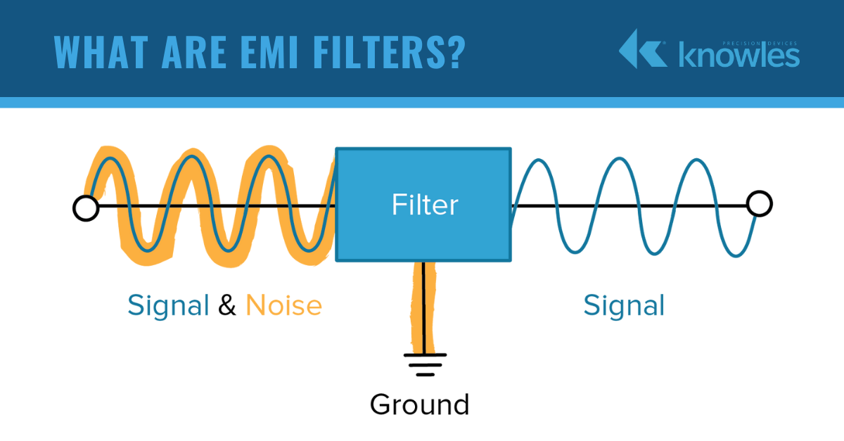
Image disclaimer: For identification and illustration only. It may show a product by another manufacturer and may not depict the exact item described; it is not a statement of any product’s quality, approval or performance. Third-party image and trademark rights belong to their owners. See full notice.
What Is It?
An EMI Filter (Electromagnetic Interference Filter) is a passive electronic component designed to attenuate conducted electromagnetic noise on power and signal lines. In airfield ground lighting systems, EMI filters are critical for ensuring that AGL equipment does not emit excessive electromagnetic radiation that could interfere with aircraft navigation systems (ILS, VOR, DME) or communication radios. They also protect sensitive control electronics from external noise sources such as switching power supplies, CCRs, and lightning‑induced transients.
Key functions of an EMI filter in AGL applications include:
- Conducted Emission Suppression: Reducing high‑frequency noise (typically 150 kHz – 30 MHz) generated by switching power supplies, LED drivers, and CCRs from propagating back onto the mains or control lines.
- Conducted Susceptibility Improvement: Protecting equipment from external noise present on the power or signal lines, preventing malfunctions or data corruption.
- Common‑Mode and Differential‑Mode Attenuation: Using a combination of inductors (chokes) and capacitors to attenuate both common‑mode noise (noise on both lines relative to ground) and differential‑mode noise (noise between the lines).
- Compliance with EMC Standards: Ensuring that AGL equipment meets international EMC standards (e.g., IEC 61000, FAA requirements) for both emission and immunity.
EMI filters are typically installed at the AC or DC input of AGL power supplies, LED drivers, and communication interfaces. They are designed to be compact, robust, and capable of operating in the extreme temperature and vibration conditions of an airfield environment.
Purpose & Function
The EMI filter's purpose is to keep the electrical noise generated by switching power supplies, LED drivers, and CCRs from propagating out onto the mains or into nearby cabling where it could interfere with aircraft navigation and communication systems — ILS, VOR, DME — operating in the immediate vicinity of the airfield. This is not a discretionary quality improvement but a compliance-driven electromagnetic-compatibility requirement, since AGL equipment sits close to systems pilots and controllers depend on for safe operation. In the other direction, the filter also protects the AGL equipment's own control electronics from external noise and lightning-induced transients on the same lines, making it a two-way safeguard against interference rather than a single-purpose suppression component.
Where Is It Used?
EMI filters are deployed throughout AGL systems wherever power conversion or signal transmission occurs:
- LED Drivers and Power Supplies: Installed at the AC or DC input of LED drivers to prevent switching noise from radiating or conducting back to the mains.
- Constant Current Regulators (CCRs): Used at the input and output stages of CCRs to suppress harmonics and conducted emissions on the series lighting circuit.
- Communication Lines: Applied to RS‑485, Ethernet, and other data lines to prevent noise pickup and reduce radiation.
- ALCMS Servers and Workstations: Installed in power supplies and network interfaces to protect control room equipment from noise and to prevent emissions from affecting other systems.
- APU and Ground Power Units: Used to filter the power output to aircraft, ensuring clean power and preventing interference with aircraft systems.
- Sensor and Monitoring Systems: Protecting analog and digital sensor inputs from noise that could cause false readings.
- Apron Guidance Systems (VDGS): Filtering power and signal lines to ensure reliable operation of sensors and displays.
EMI filters are also used in:
- Retrofit Upgrades: Adding filters to existing systems to improve EMC compliance when replacing older equipment with modern switching power supplies.
- Test and Measurement Equipment: Ensuring that measurement readings are not corrupted by conducted noise.
- Portable and Temporary AGL Systems: Providing EMC protection for mobile or temporary installations.
Installation & Location
The filter is installed inline at the input (and sometimes output) stage of the equipment it protects — inside the LED driver or power supply housing, at the CCR's incoming supply terminals, or in the enclosure of an ALCMS server or workstation — mounted close to the point where the cable enters the equipment so unfiltered noise has the shortest possible path to radiate or couple onto other wiring. Filters on data lines (RS-485, Ethernet) are fitted at the cable's entry to the equipment rather than partway along the run, and filter earthing is bonded to the equipment's own chassis/earth point rather than a separate ground, since an ineffective earth bond is the most common cause of a filter underperforming after installation.
How Does It Work?
An EMI filter typically uses a passive network of inductors and capacitors to attenuate unwanted frequencies while allowing the desired power or signal to pass:
- Common‑Mode Choke (CMC): A transformer‑like inductor with two windings wound on a common core. Common‑mode currents (flowing in the same direction on both lines) create a magnetic field that is opposed by the core, resulting in high impedance to common‑mode noise. Differential‑mode currents (flowing in opposite directions) produce opposing magnetic fields that cancel, allowing the desired signal to pass with low impedance.
- Differential‑Mode Inductors (Ldm): Series inductors on each line that create high impedance to differential‑mode noise (noise flowing between the lines). These are often implemented as separate inductors or as part of the common‑mode choke's leakage inductance.
- X‑Capacitors (Cx): Capacitors connected between the live and neutral lines (or between the + and – lines for DC). They provide a low‑impedance path for differential‑mode noise, shunting it away from the load.
- Y‑Capacitors (Cy): Capacitors connected between each line and ground (earth). They provide a low‑impedance path for common‑mode noise to ground, reducing the noise voltage on the lines relative to ground.
- Damping Resistors: Some filters include resistors to dampen resonances that could occur between the inductors and capacitors, preventing unexpected gain at certain frequencies.
- Circuit Topology: A typical EMI filter for an AGL power supply is a multi‑stage network:
- Stage 1 (Input): X‑capacitor and common‑mode choke for first‑line suppression.
- Stage 2 (Mid): Differential‑mode inductors and additional X‑capacitors for enhanced differential‑mode attenuation.
- Stage 3 (Output): Y‑capacitors to ground and a final common‑mode choke to ensure residual noise is minimised.
- Frequency Response: The filter is designed to have low insertion loss in the desired operating frequency (e.g., 50/60 Hz for AC power) and high attenuation in the frequency range where EMI is problematic (typically 150 kHz to 30 MHz for conducted emissions).
In AGL applications, EMI filters are often housed in rugged metal enclosures with proper grounding connections, and they are designed to handle the high surge currents and temperature ranges typical of airfield environments.
System Architecture & Control Logic
The EMI filter has no control logic of its own and takes no part in any command or feedback loop in the AGL system — it is a purely passive network that sits inline, physically, wherever a piece of equipment's power or data lines cross the boundary between the outside world and the equipment's internal electronics. In that sense its role in the system architecture is defined entirely by placement rather than behaviour: one filter sits at the CCR's incoming mains supply, another inside an LED driver ahead of the constant current module, another at an ALCMS server's power inlet, and another on an RS‑485 or Ethernet line entering a controller — each protecting the electronics downstream of it from noise generated elsewhere on the airfield's cabling, and each preventing noise generated by its own equipment from propagating back out onto shared power or data infrastructure. Because it neither senses nor responds to anything (there is no feedback signal, no ALCMS command, no adjustable state), the filter is best understood as a boundary condition the rest of the control architecture depends on rather than a participant in it: the CCR's current regulation, the constant current module's fast local feedback loop, and the ALCMS's command and telemetry links all assume a certain level of electrical cleanliness at their terminals, and the filter is what keeps that assumption true.
Multi‑Stage Filter Network
Physical Construction
The filter is built around a common-mode choke — two windings on a shared ferrite toroid or E-core — paired with X-capacitors bridging line-to-line and Y-capacitors bridging line-to-earth, all soldered to a small PCB or wired directly into a metal or plastic enclosure depending on the mounting style. PCB-mount versions sit inline on the driver or CCR board itself; DIN-rail and chassis-mount versions use a stamped metal case, often finned for heat dissipation at higher current ratings, with screw terminals or spade connectors for field wiring. The enclosure's IP rating (IP20 indoors up to IP67 for exposed installations) and the choke's core material are matched to the application, since a filter left exposed to moisture or vibration loses insertion loss performance well before its capacitors or windings actually fail.
Technical Parameters
| Parameter | Typical Value |
|---|---|
| Rated Voltage (AC) | 125 V, 250 V, 480 V (AC) |
| Rated Voltage (DC) | 24 V, 48 V, 120 V, 300 V (DC) |
| Rated Current | 1 A – 100 A (depending on application) |
| Attenuation (Common‑Mode) | ≥ 40 dB @ 1 MHz – 30 MHz |
| Attenuation (Differential‑Mode) | ≥ 30 dB @ 150 kHz – 30 MHz |
| X‑Capacitor Value | 0.1 µF – 1 µF (typical) |
| Y‑Capacitor Value | 1 nF – 100 nF (typical) |
| Leakage Current (Y‑Cap) | ≤ 0.5 mA (for safety) |
| Insertion Loss (50 Ω system) | Typically 30–80 dB depending on frequency |
| Operating Temperature | -40°C to +85°C |
| Protection Class | IP20 – IP67 (depending on enclosure) |
| Safety Approvals | UL, CSA, VDE, CE |
| Mounting | PCB‑mount, DIN‑rail, or chassis‑mount |
Electrical Requirements
| Requirement | Typical Value |
|---|---|
| Rated Voltage | 125V / 250V / 480V AC or 24V / 48V / 120V / 300V DC, matched to the circuit it protects |
| Rated Current | 1A – 100A, sized to the full load current of the protected circuit (CCR, LED driver, or control electronics) |
| Wiring | Installed in series with the line and neutral (or DC+/DC−) conductors, as close as practical to the protected equipment |
| Earthing/Grounding | Filter case and Y-capacitor ground leads bonded to a low-impedance protective earth |
| Leakage Current | ≤ 0.5 mA at rated voltage/frequency, verified during earth continuity/leakage testing |
| Fault Protection | Upstream fuse or circuit breaker sized to the filter's rated current |
| Mounting | PCB-mount, DIN-rail, or chassis-mount with a low-impedance bond to the equipment chassis |
| Cable Separation | Filtered (clean) and unfiltered (noisy) wiring kept physically separated to prevent noise coupling around the filter |
| Post-Install Verification | Conducted emissions testing after installation to confirm attenuation meets EMC requirements |
Applicable Standards
IEC 61000‑6‑4
EMC – Emission standard for industrial environments
IEC 61000‑6‑2
EMC – Immunity standard for industrial environments
CISPR 11 / CISPR 22
Limits and methods of measurement of EMI from industrial equipment
Installation Requirements
Inline Mounting Position
MechanicalMount the filter close to the point where the cable enters the equipment it protects — the LED driver, CCR supply terminals, or ALCMS enclosure — so unfiltered noise has the shortest possible path to radiate.
Data Line Filter Placement
ElectricalWhere fitted on data lines (RS-485, Ethernet), fit the filter at the cable's entry to the equipment rather than partway along the run.
Chassis Earth Bonding
ElectricalBond the filter's earthing to the equipment's own chassis/earth point rather than a separate ground, since an ineffective earth bond is the most common cause of underperformance.
Cable Entry Sealing
MechanicalSeal the cable entry point at the filter/equipment interface to maintain the enclosure's environmental rating.
Terminal Torque & Connection
MechanicalTorque input and output terminal connections to the manufacturer's specification for a secure, low-resistance connection.
Y-Capacitor Leakage Consideration
ElectricalConfirm the installation's earth leakage budget accounts for the filter's Y-capacitor leakage current before connection.
Pre-Energisation Sign-off
DocumentationRecord mounting position, bonding, and terminal torque before the filter and protected equipment are energised.
Testing & Commissioning
Insulation Resistance & Hipot Test
Pre-EnergisationVerify insulation resistance and dielectric withstand between live conductors and earth before the filter is connected to the supply.
Insertion Loss Verification
Functional TestMeasure insertion loss across the operating frequency band, confirming low loss at 50/60 Hz and high attenuation in the conducted-emission range.
Common-Mode/Differential-Mode Attenuation Test
Functional TestVerify the common-mode choke and differential-mode inductors attenuate noise correctly on both current paths.
Conducted Emissions Test
Functional TestMeasure conducted emissions at the filter's output against CISPR 11/22 limits to confirm the filter suppresses noise to the required level.
Leakage Current Test
Functional TestMeasure earth leakage current through the Y-capacitors, confirming it stays within the safety limit for the application.
Thermal Rise Test Under Rated Load
Functional TestRun the filter at rated current for an extended period, confirming component and enclosure temperatures stay within design limits.
Enclosure Grounding & Bonding Check
Pre-AcceptanceConfirm the enclosure is correctly bonded to earth with a low-resistance connection before the unit is accepted into service.
Documentation & As-Built Sign-off
Final AcceptanceRecord insertion loss, emissions, and thermal test results in the commissioning dossier for handover.
Inspection & Maintenance
Capacitor Condition Check
AnnualInspect filter capacitors for signs of degradation such as bulging or leakage.
Grounding Continuity Check
AnnualVerify grounding connections remain intact, since inadequate grounding undermines filter effectiveness.
Leakage Current Test
AnnualTest leakage current against the rated limit to confirm continued safe operation.
Housing & Component Inspection
AnnualCheck the filter housing and internal components for mechanical damage.
Common Field Issues
Capacitor Degradation
X‑capacitors and Y‑capacitors can degrade over time, especially in high‑temperature environments or with repeated surge events. Degraded capacitors lose capacitance and increase ESR, reducing the filter's effectiveness. Regular inspection and replacement (every 5–10 years) are recommended, especially in critical applications.
Common‑Mode Choke Saturation
If the common‑mode choke experiences high DC current or magnetic saturation, its inductance drops significantly, reducing common‑mode attenuation. This can happen if the filter is undersized for the load current or if there is a DC offset. Ensure that the filter's rated current is sufficient for the application.
Inadequate Grounding
EMI filters rely on a low‑impedance ground connection for Y‑capacitors to be effective. If the ground connection is poor (high resistance), common‑mode noise will not be effectively shunted to ground, leading to increased emissions and susceptibility. Ensure proper grounding to a dedicated earth pit with resistance < 5 Ω.
Leakage Current and Safety Concerns
Y‑capacitors contribute to leakage current, which can be a safety concern if the filter is used in a system without proper earthing. In some applications, excessive leakage current can trip residual‑current devices (RCDs). Ensure that the total leakage current of all filters in the system is within acceptable limits for the protective devices used.
Mechanical Damage
EMI filters can be damaged by physical impact, vibration, or moisture ingress. This can lead to short circuits, open circuits, or degraded performance. Inspect filters regularly for signs of cracking, corrosion, or discolouration, and replace any that show physical damage.
Troubleshooting Guide
Increased EMI Emissions or Susceptibility Over Time
Reduced Common-Mode Noise Attenuation
High Emissions Despite a Healthy Filter
RCD/Residual-Current Device Nuisance Tripping
Filter Shows Physical Damage or Discolouration
Failure Modes & Root Causes
Capacitor Degradation
Common-Mode Choke Saturation
Ground Connection Degradation
Aggregate Leakage Current Exceedance
Housing Damage
Safety & Operational Notes
Residual Charge Discharge Before Handling
Electrical SafetyDischarge the filter's internal X/Y capacitors before handling terminals, even after the circuit has been de-energised; these capacitors can retain a hazardous charge for some time after power is removed.
Ground Connection Integrity Verification
Electrical SafetyVerify the filter's earth connection is sound before returning it to service; the filter's leakage-current path depends on a solid ground, and a floating or high-resistance earth turns a protective device into a shock hazard.
Aggregate Leakage Current Compliance
Electrical SafetyPeriodically verify the combined leakage current of all EMI filters sharing a supply stays within the applicable touch-current limit, particularly after adding equipment to a circuit that already has filters installed.
Circuit Isolation Before Servicing
Electrical SafetyDe-energise and lock out the supply before opening a filter's housing or disconnecting it for replacement, and verify zero energy before touching any terminal.
Use Only Certified Replacement Filters
OperationalReplace a failed filter only with a unit of the same certified type and rating; the filter exists to keep AGL equipment from radiating interference into ILS, VOR, DME, and radio frequencies, and a mismatched substitute can silently reintroduce that risk.
PPE / Insulated Tools
Personnel SafetyUse insulated tools and appropriate PPE when working on filter terminals, and treat every filter as potentially carrying a residual charge until it has been confirmed discharged.
Engineering & Expert Notes
Aggregate Leakage Adds Up Across a Loop
DesignA single filter's leakage current is trivial against the touch-current limit, but a series circuit with dozens of filtered fixtures can accumulate a surprising total at the CCR end. Sum expected leakage across the whole loop at design stage rather than checking each filter in isolation and assuming compliance follows.
Filter Selection Follows the Interference Source, Not Just the Load
ElectricalAn EMI filter chosen purely on current rating can still let through the specific switching-frequency noise an LED driver or CCR generates. Match the filter's attenuation curve to the actual harmonic content of the equipment it protects, especially near ILS or VOR-critical areas where the tolerance for radiated interference is tightest.
Nuisance RCD Trips Often Trace Back Here
TroubleshootingIntermittent RCD/ELCB trips on a circuit with multiple filtered devices are frequently a cumulative-leakage issue rather than a genuine earth fault. Before chasing an insulation fault across the whole loop, check whether the trip threshold is simply being approached by the combined filter leakage.
Capacitor Ageing Shows Up as Filtering Loss First
ReliabilityX/Y capacitors inside a filter degrade gradually with heat and voltage stress well before they fail outright; the earliest symptom is usually reduced attenuation rather than a hard fault. Where nearby navigation aids report rising interference with no obvious cause, ageing filters are worth checking before assuming a new noise source.
A Failed Filter Should Fail Safe, Not Silent
MaintenanceConfirm what actually happens on internal filter failure for the specific model in use; some fail open (equipment stops, fault is obvious) while others can fail in a way that quietly removes filtering while the circuit keeps running. Know which behaviour your installed filters have before relying on "no complaints" as proof of health.
Keep Filtered and Unfiltered Wiring Separated
InstallationRunning filtered output cabling alongside unfiltered input cabling in the same duct or gland plate can recouple the very noise the filter just removed. Route input and output sides with physical separation, not just electrical isolation on paper.
Frequently Asked Questions
Short answers about EMI filters in AGL systems: function, components, standards and maintenance.
Q1What is an EMI filter?
An EMI (electromagnetic interference) filter is a passive component that attenuates conducted electromagnetic noise on power and signal lines, protecting AGL equipment and nearby systems.
Q2Where are EMI filters used in AGL systems?
At the input of LED drivers and power supplies, on the input and output stages of CCRs to suppress harmonics, on RS-485, Ethernet and other communication lines, and in ALCMS servers and workstations.
Q3How does an EMI filter work?
A passive network of inductors and capacitors passes the wanted power or signal and blocks unwanted frequencies. It uses a common-mode choke, differential-mode inductors, X-capacitors between the lines and Y-capacitors to earth.
Q4What is the difference between common-mode and differential-mode noise?
Differential-mode noise flows between the two lines, while common-mode noise flows in the same direction on both lines relative to earth. The filter treats each with different components: X-capacitors and series inductors for differential mode, and the common-mode choke and Y-capacitors for common mode.
Q5What are typical EMI filter ratings?
Rated voltages of 125 V, 250 V or 480 V AC and 24 V to 300 V DC, with currents of 1 A to 100 A. The page gives common-mode attenuation of at least 40 dB from 1 to 30 MHz.
Q6Which standards apply to EMI filters?
The main references are IEC 61000-6-4 (emissions) and IEC 61000-6-2 (immunity) for industrial environments, and CISPR 11 and CISPR 22 for measurement limits.
Q7How often should an EMI filter be checked?
Annually. Inspect capacitors for bulging or leakage, verify grounding continuity, and test leakage current against the rated limit.
Q8What are the common problems with EMI filters?
Capacitor degradation, common-mode choke saturation under high DC current, inadequate grounding that undermines the Y-capacitors, and mechanical damage or moisture ingress.
Related Components
Go Beyond the Component. Understand the Complete AGL System.
You have explored the component. Now understand how it works within the complete Airfield Ground Lighting system.
Learn AGL from fundamentals to design, installation, testing, photometry, commissioning, maintenance and troubleshooting through structured technical training at Precision AGL Academy.
Build practical knowledge. Understand the circuit. Read the standards. Troubleshoot with confidence.
Your next step in AGL starts here.
Need expert guidance on EMI filter selection or EMC compliance?
Precision AGL Academy provides advice on filter specification, placement, grounding, and compliance with international EMC standards for AGL systems.
Follow the Academy
Important Notice, Disclaimer & Limitation of Liability
Please read before relying on any content on this page.
- Purpose and intended users. This page on EMI Filter is an independent educational and informational reference for competent, suitably trained and authorised airfield ground lighting (AGL) and aerodrome electrical personnel. It is not professional engineering, legal or regulatory advice, and using it does not create any professional or client relationship.
- Safety. Work on series circuits, constant current regulators (CCRs), isolating transformers, cables, connectors and lighting equipment can be fatal. Always apply the aerodrome’s permit-to-work and isolation/LOTO procedures, prove dead, use correctly rated instruments and PPE, and follow the manufacturer’s instructions. Nothing here authorises work on live equipment or the bypassing of any safety device or interlock.
- Aviation operations. Nothing here authorises installation, modification, energisation, adjustment, return to service, a change of operating category (CAT I/II/III), a NOTAM or any aerodrome certification or approval decision. These rest with the aerodrome operator, the air navigation service provider and the competent regulator.
- Specifications, ratings and typical values. Descriptions, parameters, ratings, dimensions, photometric values, wattages, service lives, maintenance tasks and intervals, failure modes, certifications (for example CE, FCC, UL or IEC marks) and part or type designations are general, typical and indicative. They may not match any particular product, make, model or version, and they are not a datasheet, design, specification, selection, sizing, procurement or acceptance criterion. The manufacturer’s current documents, the approved design and the project specification prevail.
- Standards and regulations. References to ICAO, FAA, IEC, IEEE, ISO, BIS, DGCA and other standards are paraphrased summaries for orientation only. They may be incomplete or out of date, and standards are revised from time to time. Consult the current official editions. Following this content does not guarantee compliance with any law, standard or regulatory approval, and the regulator’s requirements always prevail.
- No warranty. Content is provided “as is” and “as available”, without warranty of any kind, express or implied, including accuracy, completeness, currency or fitness for a particular purpose. Real installations differ in design, equipment make and model, age and condition.
- Limitation of liability. To the fullest extent permitted by applicable law, Precision AGL Academy, Precision AGL Solutions and their owners, authors and contributors are not liable for any injury, death, loss, damage, downtime, penalty or regulatory consequence, whether direct or indirect, arising from the use of, reliance on, or inability to use this content. Nothing in this notice excludes or limits any liability that cannot lawfully be excluded or limited.
- Independence, brands and no endorsement. This is an independent publication. It is not affiliated with, sponsored by or endorsed by ICAO, the FAA, the IEC, DGCA, AAI, any airport, regulator, supplier or equipment manufacturer. Third-party names, product designations, standard designations and trademarks (including Megger®, Siemens, Eaton, Crouse-Hinds, ADB SAFEGATE, Fluke, ABB and Honeywell) belong to their respective owners and are used only for identification and description. Mention of a brand, product or supplier is not a recommendation, and we do not sell, supply or quote for any component described.
- Images and third-party content. Images and illustrations are shown to help identify the type of component. They may show products of various manufacturers, may not depict the exact item described, and are not a statement about any product’s quality, approval or performance. Copyright and trademarks in third-party images, logos and photographs belong to their respective owners and are not claimed as ours. If you are a rights holder and want an image removed, replaced or credited, email precisionaglsolutions@gmail.com with the page address and we will act promptly.
- Training and services. Mentions of training, courses, consultation, advice, selection, installation, calibration or other support, including the “Learn…Certify” pathway, describe learning stages and are not an offer, quotation, tender or promise of any result. Contacting us or our replying creates no engagement or duty of care; an engagement exists only under a written agreement. We are not a regulator or certification body, and completing any course or reading this content is not a certification, accreditation or authorisation to work on any aerodrome.
- Copyright, privacy and corrections. © 2026 Precision AGL Academy. All rights reserved. Text, structure, compilations and diagrams may be viewed for personal reference and internal training only; any other copying, republication or commercial use needs our written permission. If you email, telephone or message us, we use your details only to respond and handle your matter, in line with applicable Indian law including the Digital Personal Data Protection Act, 2023; please do not send confidential or security-sensitive information. To display this page your browser requests fonts, icons and images from third-party servers, which receive your IP address and browser details under their own policies. Content is reviewed periodically with no obligation to update. To report an error, safety concern or rights issue, write to precisionaglsolutions@gmail.com.