Surge Protection Device (SPD)
A critical protective device that safeguards Airfield Ground Lighting (AGL) equipment from transient overvoltages caused by lightning strikes, switching operations, and other electrical disturbances. SPDs are essential for ensuring the reliability and longevity of sensitive AGL electronics, including Constant Current Regulators (CCRs), LED drivers, communication modules, and control systems.
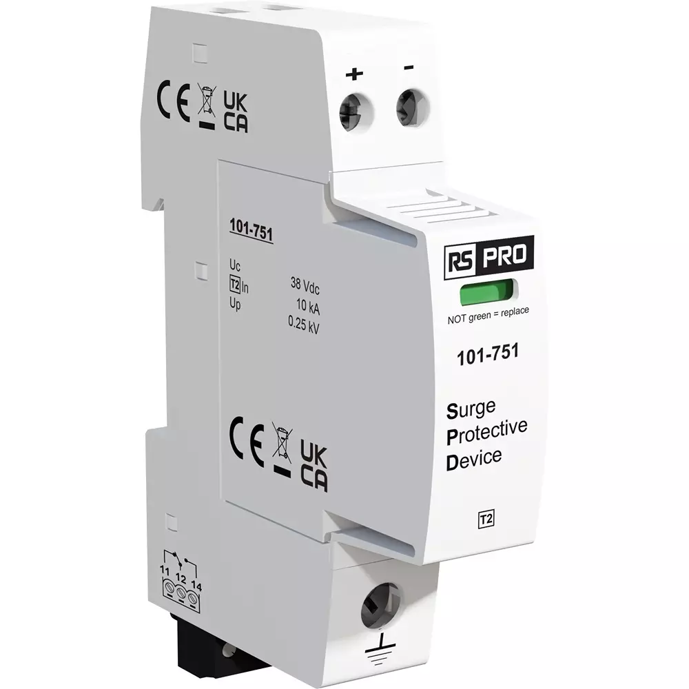
Image disclaimer: For identification and illustration only. It may show a product by another manufacturer and may not depict the exact item described; it is not a statement of any product’s quality, approval or performance. Third-party image and trademark rights belong to their owners. See full notice.
What Is It?
A Surge Protection Device (SPD) is a protective component designed to limit transient overvoltages and divert surge currents to earth, thereby protecting downstream equipment from damage. In AGL systems, SPDs are installed at critical points such as:
- AC Mains Input: Protecting the entire AGL substation or CCR room from external surges originating from the utility grid.
- CCR Outputs: Protecting series lighting circuits from lightning‑induced surges on the airfield.
- Control and Communication Lines: Protecting ALCMS, PLC, and data networks from surges induced on signal cables.
- LED Fixtures: Many modern AGL luminaires have built‑in SPDs to protect the LED drivers from surges on the secondary circuit.
SPDs are classified into three types (according to IEC 61643‑11): Type 1 (for direct lightning strike protection), Type 2 (for indirect surges), and Type 3 (for sensitive equipment protection). AGL installations typically use a combination of these types in a coordinated cascade.
Purpose & Function
The surge protection device's purpose is to intercept the transient overvoltages that lightning strikes and grid switching events induce on power and signal lines, clamping them to a safe level before they reach the CCRs, LED drivers, and control electronics that are otherwise vulnerable to this kind of damage. Because these transients typically last only microseconds but carry enough energy to destroy solid-state components instantly, the SPD's role is to react fast enough and absorb enough energy to prevent that damage in the first place, rather than simply detecting or reporting a fault after it has already occurred. Deploying SPDs in a coordinated cascade — a robust Type 1 device at the main supply, progressively more sensitive Type 2 and Type 3 devices closer to the equipment — is what allows each stage to handle the portion of surge energy it is designed for, protecting increasingly delicate electronics the deeper into the system a surge travels.
Where Is It Used?
SPDs are used at multiple levels within the AGL electrical infrastructure:
- At the Main Distribution Panel: Type 1 or Type 2 SPDs protect the entire AGL power supply from external surges (lightning, grid switching).
- At CCR Input and Output: SPDs on the input side protect the CCR from mains surges; on the output side, they protect the series loop from induced surges (especially in exposed airfield locations).
- At Remote Lighting Control Panels: Protecting sub‑distribution circuits feeding individual runway/taxiway sections.
- At Communication and Data Lines: Protecting Ethernet, fiber optic (with metallic conductors), RS‑485, and other control signals.
- Within LED Fixtures: Many modern LED AGL lights include built‑in SPDs to protect the LED driver and optics.
Installation & Location
SPDs are DIN-rail or panel-mounted at the specific point in the circuit they protect, rather than at a single dedicated location — units are fitted at the main distribution panel's incoming feeder, at the input and output terminals of each CCR, in remote lighting control panels, and inline on communication and data cables entering equipment cabinets. Lead lengths to the protected busbar or terminal are kept as short and direct as practical, since excessive lead length reduces clamping effectiveness, and each SPD's earth conductor is bonded to the panel's earth bar with as short and low-impedance a path as the enclosure allows. Where an SPD is built into an LED fixture, it sits inside the fixture housing ahead of the LED driver, requiring no separate installation beyond the fixture itself.
How Does It Work?
An SPD operates by diverting surge energy away from the protected circuit and safely to earth. The operating principles depend on the technology used:
- Metal Oxide Varistor (MOV): The most common technology. MOVs have a high resistance at normal voltage but become highly conductive when the voltage exceeds the clamping level (breakdown voltage). They absorb surge energy and dissipate it as heat.
- Gas Discharge Tube (GDT): A spark gap filled with inert gas. At normal voltage, the gas is non‑conductive. When a surge exceeds the breakdown voltage, the gas ionizes and conducts the surge current to ground. GDTs handle very high surges (Type 1) but have a slower response.
- Transient Voltage Suppression (TVS) Diode: A solid‑state device that clamps voltage to a fixed level. It has a very fast response (< 1 ns) and is used for sensitive electronics (Type 3).
- Combined SPDs: Often incorporate multiple technologies (e.g., GDT + MOV + TVS) to provide both high energy handling and fast response.
- Sequential Protection: In practice, a cascade of SPDs (Type 1 at the main panel, Type 2 at sub‑distribution, Type 3 at equipment) ensures that the surge energy is progressively reduced before reaching sensitive electronics.
System Architecture & Control Logic
An SPD is a passive protective device with no active control loop of its own — its "logic" lies entirely in its clamping characteristic, diverting transient overvoltage to earth once the let-through voltage threshold is exceeded, then resetting to a high-impedance state once the transient passes. Its role in the wider control architecture is as a monitored protective element: most airfield-grade SPDs include a status indicator, a visual flag and/or a dry contact, that changes state once the internal protection element has been consumed by repeated or severe surges. That contact is typically wired back to the alarm panel or a SCADA/monitoring system, so a failed or end-of-life SPD is reported for replacement rather than silently leaving the downstream equipment unprotected.
Transient Event → SPD Clamping → Diverted Energy → Status Contact → Alarm Panel / SCADA
Surge Energy Cascade: Panel to Equipment
Surge Enters
Lightning-induced or switching transient on the AC mains
Type 1 SPD
Main panel · GDT · 10kA (10/350µs) · absorbs bulk energy
Type 2 SPD
Sub-distribution · MOV · 20kA (8/20µs) · clamps residual surge
Type 3 SPD
Equipment level · TVS diode · <1ns response · fine clamp
Equipment Protected
Voltage held below the damage threshold at every stage
Physical Construction
The SPD is built as a modular DIN-rail cartridge: a plastic housing contains the protection elements — metal-oxide varistors (MOVs), gas discharge tubes (GDTs), or a hybrid combination depending on the protection type — potted or securely mounted to withstand the thermal and mechanical stress of repeated surge events. The cartridge plugs into a fixed base that remains wired into the circuit, so a degraded module can be swapped without disconnecting the protected conductors, and a mechanical flag or remote contact on the module face indicates end-of-life so a failed unit is visually identifiable during inspection. Terminals are screw-clamp, sized for the current rating of the protected circuit, and the DIN-rail base includes an integral earth connection bar to provide the low-impedance path to ground the device depends on to divert surge current effectively. The housing is rated for the same wide temperature range as other DIN-rail control-cabinet equipment, reflecting its typical installation alongside CCRs, PLCs, and other AGL electronics in the same enclosure.
Technical Parameters
| Parameter | Typical Value |
|---|---|
| Type (IEC 61643‑11) | Type 1 (direct strike), Type 2 (indirect), Type 3 (equipment protection) |
| Nominal Voltage (Un) | 230V, 400V AC (depending on system) |
| Maximum Continuous Operating Voltage (Uc) | 255V – 275V AC (230V systems), up to 440V AC (400V three‑phase systems) |
| Surge Current Capacity (Iimp or In) | Type 1: 10kA (10/350 µs), Type 2: 20kA (8/20 µs), Type 3: 3kA (8/20 µs) |
| Voltage Protection Level (Up) | ≤ 1.5 kV (for equipment protection), ≤ 2.5 kV (for main protection) |
| Response Time | < 1 ns (TVS diode), < 25 ns (MOV), ~100 ns (GDT, waveform‑dependent) |
| Poles | 1‑pole, 2‑pole, 3‑pole, 4‑pole (for AC systems) |
| Mounting | DIN rail (35mm) for modular SPDs; plug‑in modules for easy replacement |
| Operating Temperature | ‑40°C to +85°C |
| End of Life Indication | Mechanical flag or remote signal contacts (for monitoring) |
| Standards Compliance | IEC 61643‑11, UL 1449, IEEE C62.41 (referenced within FAA equipment ACs such as AC 150/5345‑10 and AC 150/5345‑54) |
Electrical Requirements
| Requirement | Typical Value |
|---|---|
| Nominal System Voltage (Un) | 230V or 400V AC, matched to the protected circuit |
| Backup Fuse/Breaker | Sized per manufacturer's coordination table to clear a failed SPD without nuisance tripping the main breaker |
| Connection Point | Installed at the main distribution board (Type 1/2) and/or at equipment level (Type 3), as close as practical to the protected load |
| Cabling | Short, straight connecting leads to minimise let-through voltage from added lead inductance |
| Earthing/Grounding | Short, low-impedance bond to the main earthing busbar — critical to the device's protection level |
| End-of-Life Monitoring | Mechanical flag or remote signal contact wired to ALCMS/BMS for replacement alerting |
| Mounting | 35mm DIN rail, modular plug-in base for tool-free replacement |
Applicable Standards
IEC 61643‑11
Low‑voltage surge protective devices – Requirements and test methods
UL 1449
Surge Protective Devices – Safety standard
IEEE C62.41
Recommended practice on surge voltages in low‑voltage AC power circuits
FAA Equipment ACs
AC 150/5345‑10 (CCRs), AC 150/5345‑54 (PCUs) and similar equipment specs mandate lightning/surge arresters tested to IEEE C62.41 — the FAA has no standalone SPD advisory circular
Installation Requirements
DIN-Rail or Panel Mounting
MechanicalMount each SPD at the specific point in the circuit it protects — the main distribution panel's incoming feeder, CCR input/output terminals, remote lighting control panels, or inline on communication and data cables entering equipment cabinets.
Short Lead Length Routing
ElectricalKeep lead lengths to the protected busbar or terminal as short and direct as practical, since excessive lead length reduces clamping effectiveness.
Low-Impedance Earth Bonding
ElectricalBond each SPD's earth conductor to the panel's earth bar with as short and low-impedance a path as the enclosure allows.
Fixture-Integrated SPD Check
ElectricalWhere an SPD is built into an LED fixture ahead of the driver, confirm it is factory-fitted and requires no separate installation beyond the fixture itself.
Pre-Commissioning Sign-off
DocumentationRecord SPD location, lead lengths, and earth bonding as-built before the protected circuit is energised.
Testing & Commissioning
Status Indicator Verification
Pre-EnergisationConfirm the mechanical flag or remote contact on each new module reads healthy before the circuit is energised.
Earth Bond Continuity Test
Pre-EnergisationVerify low-impedance continuity from the DIN-rail earth bar to the site earthing system, since the SPD's clamping performance depends on it.
Type & Rating Verification
Pre-EnergisationConfirm the installed cartridge matches the specified Type 1/2/3 protection category and current rating for its position in the cascade.
Remote Contact / SCADA Signal Test
EnergisationTrip or simulate an end-of-life state and confirm the alarm reaches the panel or SCADA/monitoring system correctly.
Cascade Coordination Check
Final AcceptanceConfirm Type 1/2/3 devices are correctly sequenced along the circuit so energy is progressively reduced before reaching sensitive equipment.
Terminal Torque Check
Pre-EnergisationVerify screw-clamp terminals are torqued to spec, since a loose connection undermines the low-impedance path the device relies on.
Documentation & As-Built Sign-off
Final AcceptanceRecord device type, rating, position, and status-indicator condition for each installed SPD in the commissioning dossier for handover.
Inspection & Maintenance
End-of-Life Indicator Check
QuarterlyVisually verify the status indicator and replace the SPD immediately if it shows an end-of-life or tripped state.
Earthing System Continuity Check
AnnualVerify earth bond integrity and confirm the earthing path resistance remains within the required limit.
SPD Type & Rating Verification
At install / replacementConfirm the installed device matches the correct protection category and rating for its position in the circuit.
Common Field Issues
Incorrect SPD Type Selection
Using a Type 3 SPD at the main panel (where high energy surges are expected) will result in failure. Always select the appropriate type based on the location and risk level. A cascade approach (Type 1 → Type 2 → Type 3) is recommended.
Poor Earthing System
An SPD is only as effective as the earthing system to which it is connected. High‑impedance earth connections reduce surge diversion effectiveness. Ensure proper earthing (low resistance) and inspect connections regularly.
End‑of‑Life Indicator Ignored
Many SPDs have mechanical or remote indicators that show when the protection element has degraded (e.g., MOVs have a limited number of surge events). Ignoring these indicators can leave equipment unprotected. Replace SPDs when indicated.
Voltage Protection Level (Up) Too High
If the SPD's clamping voltage is higher than the withstand voltage of downstream equipment, the equipment may still be damaged. Always verify that Up is compatible with the protected equipment's insulation rating.
Troubleshooting Guide
SPD Fails Shortly After a Surge Event
Poor Surge Diversion Despite a Healthy SPD
Equipment Remains Unprotected After Multiple Surge Events
Downstream Equipment Damaged Despite an SPD Being Present
SPD Indicator Shows Fault But the Circuit Still Operates
Failure Modes & Root Causes
MOV / Protection Element End-of-Life Degradation
Earthing System Continuity Failure
Incorrect SPD Type / Rating Selection
Cascade Coordination Failure
Repeated Surge Event Cumulative Wear
End-of-Life Indicator Ignored
Safety & Operational Notes
Isolate the Protected Circuit Before Replacement
Electrical SafetyDe-energise and lock out the circuit the SPD is connected to before removing or replacing it, and verify zero energy at the terminals, since the device sits directly across live conductors.
Degraded SPD May Be Hot or Have Vented
Personnel SafetyTreat an SPD that has tripped its end-of-life indicator or absorbed a major surge as potentially hot or internally damaged; handle it as a failed electrical component, not a routine part, and avoid assuming it's safe to touch immediately after a fault.
Confirm Correct Replacement Rating
ComplianceReplace a failed SPD with one matched to the same nominal voltage, discharge current, and protection class as specified for that point in the system; an undersized or mismatched replacement leaves the downstream equipment under-protected.
Earthing Continuity Verification
Electrical SafetyConfirm the SPD's earth connection has low, continuous resistance before and after replacement, since a surge-protection device is only effective if its path to earth is intact.
Minimise Time Without Protection
OperationalWhere the SPD protects a CCR room, substation, or series-circuit output, coordinate the replacement to minimise the time the protected equipment is left without surge protection, particularly during storm season.
Restore to Compliant State
ComplianceVerify the new or repaired SPD's status indicator shows healthy and the protected circuit is functioning normally before closing out the work.
Engineering & Expert Notes
Degradation Without Failure Is the Normal Life Cycle
ReliabilityAn SPD's varistor or gas-discharge element degrades incrementally with every surge event it absorbs, whether or not that surge was large enough to trip the end-of-life indicator; treat SPDs on circuits with a known lightning-exposure history as candidates for proactive replacement on a service-life schedule rather than waiting for the indicator to trip.
A Cluster of Trips After One Storm Is a Data Point, Not Noise
ReliabilityWhere several SPDs across a site trip in the same storm event, record which positions were involved rather than just replacing and moving on; a repeated pattern at the same locations points to a systemic earthing or lightning-protection weakness at those points, not simple bad luck.
Earth Impedance, Not Just Continuity, Determines Effectiveness
ElectricalA simple continuity check confirms the SPD's earth path exists but says nothing about its impedance under a fast-rising surge current; where surge activity is frequent, periodic earth resistance testing gives a much better indication of actual protection effectiveness than continuity alone.
Coordinate Protection Stages, Don't Just Match Ratings Locally
DesignWhere SPDs are deployed in stages (service entrance, distribution, equipment level), replacing one stage with a device that doesn't coordinate properly with the others can leave a let-through voltage gap that no single device catches; check the manufacturer's coordination requirements across stages, not just the rating of the unit being replaced.
Thermal Runaway Risk Rises With Age, Not Just Surge Count
Failure ModeAn aged varistor can enter thermal runaway from sustained overvoltage that a fresh unit would handle without incident, since its leakage current increases as it degrades; don't assume an SPD's age alone is benign just because it hasn't tripped its indicator or visibly failed.
Keep a Replacement Log Tied to Storm Events
MaintenanceRecording the date and approximate storm severity alongside each SPD replacement builds a usable history for identifying which circuits or positions are chronically under-protected; a replacement log with no context beyond "replaced" loses this diagnostic value over time.
Related Components
Frequently Asked Questions
Short answers about surge protection devices: types, placement, ratings, earthing, standards and selection.
Q1What is a surge protection device (SPD) in AGL?
An SPD limits transient overvoltages and diverts surge currents to earth, protecting downstream equipment such as Constant Current Regulators (CCRs), LED drivers, communication modules and control systems. Transients from lightning and switching typically last only microseconds but carry enough energy to destroy solid-state components.
Q2What are the types of SPD?
IEC 61643-11 defines Type 1 (direct lightning strike protection), Type 2 (indirect surges) and Type 3 (sensitive equipment protection). AGL installations typically use a coordinated cascade of all three: Type 1 at the main panel, Type 2 at sub-distribution and Type 3 at the equipment.
Q3Where are SPDs installed in an AGL system?
At the main distribution panel's incoming feeder, at CCR inputs and outputs, at remote lighting control panels, and on communication and data lines such as Ethernet, RS-485 and fibre with metallic conductors. Many modern LED AGL luminaires also have built-in SPDs protecting the LED driver.
Q4How does an SPD work?
It diverts surge energy away from the protected circuit to earth. Common technologies are the metal oxide varistor (MOV), gas discharge tube (GDT) and transient voltage suppression (TVS) diode. Combined SPDs use several (for example GDT + MOV + TVS) to get both high energy handling and fast response.
Q5What are typical SPD ratings?
Typical nominal voltage is 230 V or 400 V AC. Surge current capacity is about 10 kA (10/350 µs) for Type 1, 20 kA (8/20 µs) for Type 2 and 3 kA (8/20 µs) for Type 3. Voltage protection level (Up) is at or below 1.5 kV for equipment protection and at or below 2.5 kV for main protection. Modular units mount on 35 mm DIN rail.
Q6Why does earthing matter so much for an SPD?
An SPD is only as effective as the earthing system it connects to. A high-impedance earth connection reduces surge diversion. Keep connecting leads short and straight, and bond the SPD to the main earthing busbar with a short, low-impedance path.
Q7How do I know when an SPD needs replacing?
Many SPDs have a mechanical flag or remote signal contact showing end of life, which can be wired to the ALCMS or BMS for alerts. MOVs have a limited number of surge events, so ignoring the indicator leaves equipment unprotected. A degraded SPD may be hot or have vented, so isolate the circuit before touching it.
Q8What backup protection does an SPD need?
A backup fuse or breaker sized to the manufacturer's coordination table, so a failed SPD is cleared without nuisance-tripping the main breaker.
Q9Which standards apply to SPDs?
The main references are IEC 61643-11, UL 1449 and IEEE C62.41. FAA equipment ACs such as AC 150/5345-10 (CCRs) and AC 150/5345-54 (PCUs) require lightning and surge arresters tested to IEEE C62.41, and the FAA has no standalone SPD advisory circular. Always verify the current edition.
Q10What are the common SPD selection and installation mistakes?
The common mistakes are using the wrong type (for example a Type 3 SPD at the main panel, where it will fail), poor earthing, ignoring the end-of-life indicator, and a voltage protection level (Up) higher than the withstand voltage of the downstream equipment.
Go Beyond the Component. Understand the Complete AGL System.
You have explored the component. Now understand how it works within the complete Airfield Ground Lighting system.
Learn AGL from fundamentals to design, installation, testing, photometry, commissioning, maintenance and troubleshooting through structured technical training at Precision AGL Academy.
Build practical knowledge. Understand the circuit. Read the standards. Troubleshoot with confidence.
Your next step in AGL starts here.
Need expert guidance on surge protection selection, coordination, or troubleshooting?
Precision AGL Academy provides advice on SPD type selection, cascade coordination, and earthing system integration for AGL installations.
Follow the Academy
Important Notice, Disclaimer & Limitation of Liability
Please read before relying on any content on this page.
- Purpose and intended users. This page on Surge Protection Device (SPD) is an independent educational and informational reference for competent, suitably trained and authorised airfield ground lighting (AGL) and aerodrome electrical personnel. It is not professional engineering, legal or regulatory advice, and using it does not create any professional or client relationship.
- Safety. Work on series circuits, constant current regulators (CCRs), isolating transformers, cables, connectors and lighting equipment can be fatal. Always apply the aerodrome’s permit-to-work and isolation/LOTO procedures, prove dead, use correctly rated instruments and PPE, and follow the manufacturer’s instructions. Nothing here authorises work on live equipment or the bypassing of any safety device or interlock.
- Aviation operations. Nothing here authorises installation, modification, energisation, adjustment, return to service, a change of operating category (CAT I/II/III), a NOTAM or any aerodrome certification or approval decision. These rest with the aerodrome operator, the air navigation service provider and the competent regulator.
- Specifications, ratings and typical values. Descriptions, parameters, ratings, dimensions, photometric values, wattages, service lives, maintenance tasks and intervals, failure modes, certifications (for example CE, FCC, UL or IEC marks) and part or type designations are general, typical and indicative. They may not match any particular product, make, model or version, and they are not a datasheet, design, specification, selection, sizing, procurement or acceptance criterion. The manufacturer’s current documents, the approved design and the project specification prevail.
- Standards and regulations. References to ICAO, FAA, IEC, IEEE, ISO, BIS, DGCA and other standards are paraphrased summaries for orientation only. They may be incomplete or out of date, and standards are revised from time to time. Consult the current official editions. Following this content does not guarantee compliance with any law, standard or regulatory approval, and the regulator’s requirements always prevail.
- No warranty. Content is provided “as is” and “as available”, without warranty of any kind, express or implied, including accuracy, completeness, currency or fitness for a particular purpose. Real installations differ in design, equipment make and model, age and condition.
- Limitation of liability. To the fullest extent permitted by applicable law, Precision AGL Academy, Precision AGL Solutions and their owners, authors and contributors are not liable for any injury, death, loss, damage, downtime, penalty or regulatory consequence, whether direct or indirect, arising from the use of, reliance on, or inability to use this content. Nothing in this notice excludes or limits any liability that cannot lawfully be excluded or limited.
- Independence, brands and no endorsement. This is an independent publication. It is not affiliated with, sponsored by or endorsed by ICAO, the FAA, the IEC, DGCA, AAI, any airport, regulator, supplier or equipment manufacturer. Third-party names, product designations, standard designations and trademarks (including Megger®, Siemens, Eaton, Crouse-Hinds, ADB SAFEGATE, Fluke, ABB and Honeywell) belong to their respective owners and are used only for identification and description. Mention of a brand, product or supplier is not a recommendation, and we do not sell, supply or quote for any component described.
- Images and third-party content. Images and illustrations are shown to help identify the type of component. They may show products of various manufacturers, may not depict the exact item described, and are not a statement about any product’s quality, approval or performance. Copyright and trademarks in third-party images, logos and photographs belong to their respective owners and are not claimed as ours. If you are a rights holder and want an image removed, replaced or credited, email precisionaglsolutions@gmail.com with the page address and we will act promptly.
- Training and services. Mentions of training, courses, consultation, advice, selection, installation, calibration or other support, including the “Learn…Certify” pathway, describe learning stages and are not an offer, quotation, tender or promise of any result. Contacting us or our replying creates no engagement or duty of care; an engagement exists only under a written agreement. We are not a regulator or certification body, and completing any course or reading this content is not a certification, accreditation or authorisation to work on any aerodrome.
- Copyright, privacy and corrections. © 2026 Precision AGL Academy. All rights reserved. Text, structure, compilations and diagrams may be viewed for personal reference and internal training only; any other copying, republication or commercial use needs our written permission. If you email, telephone or message us, we use your details only to respond and handle your matter, in line with applicable Indian law including the Digital Personal Data Protection Act, 2023; please do not send confidential or security-sensitive information. To display this page your browser requests fonts, icons and images from third-party servers, which receive your IP address and browser details under their own policies. Content is reviewed periodically with no obligation to update. To report an error, safety concern or rights issue, write to precisionaglsolutions@gmail.com.