Digital Input Module
A high‑density, DIN‑rail mounted module that interfaces binary field signals — such as switch states, alarm contacts, and status indicators — to a PLC, remote I/O, or ALCMS. The Digital Input Module provides galvanic isolation, signal conditioning, and diagnostic feedback, enabling reliable monitoring of airfield lighting equipment and control system status.
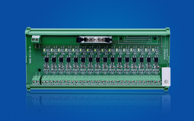
Image disclaimer: For identification and illustration only. It may show a product by another manufacturer and may not depict the exact item described; it is not a statement of any product’s quality, approval or performance. Third-party image and trademark rights belong to their owners. See full notice.
What Is It?
A Digital Input Module (DI Module) is a fundamental building block of industrial control systems, designed to capture and condition binary (on/off) signals from field devices. In AGL applications, DI modules are used to monitor the state of switches, relays, contactors, circuit breakers, and alarm contacts, providing the PLC or ALCMS with real‑time status information for control logic, alarm annunciation, and system visualisation.
Key characteristics of the Digital Input Module include:
- Multiple Input Channels: Each module typically provides 8, 16, or 32 input points, allowing high‑density monitoring of numerous field signals.
- Signal Conditioning: The module accepts a wide range of input voltages (e.g., 24 VDC, 120 VAC, 230 VAC) and converts them to a logic‑level signal (typically 5 V or 24 VDC) that the controller can process.
- Galvanic Isolation: Opto‑couplers provide electrical isolation between the field wiring and the control logic, protecting the controller from voltage spikes, surges, and ground loops.
- Diagnostic Features: Many modules include channel‑level status LEDs, blown‑fuse detection, open‑wire detection, and short‑circuit protection for enhanced troubleshooting.
- Filtering and Debouncing: Built‑in software or hardware filters eliminate contact bounce and noise, ensuring reliable signal acquisition from mechanical switches and relays.
- Field‑Removable Terminals: Spring‑clamp or screw terminals with pluggable connectors allow for easy wiring and module replacement without re‑terminating field wires.
In airfield lighting systems, DI modules are extensively used to monitor CCR status (ON/OFF, fault), circuit breaker states, lamp failure detection, and auxiliary contact feedback from contactors and relays. They are a critical component of the ALCMS data acquisition infrastructure.
Purpose & Function
The digital input module's purpose is to give the control system a continuously updated, accurate picture of the actual state of switches, breakers, and contacts across the airfield — not what the system commanded, but what genuinely happened in response. This distinction matters directly for safety and reliability: a contactor's auxiliary contact confirms it actually closed, a tripped breaker's status confirms power was actually lost, and a door contact confirms a cabinet was actually opened, none of which the control system could otherwise know with certainty. Its debounce filtering and isolation exist to make that picture trustworthy — filtering out the electrical noise of a mechanical switch settling and the surges that field wiring can pick up — so that the status the ALCMS displays and acts on reflects the real state of the airfield rather than an electrical artefact.
Where Is It Used?
Digital Input Modules are deployed throughout the AGL control infrastructure wherever binary status monitoring is required. Key applications include:
- CCR Status Monitoring: Reading the ON/OFF state, fault contacts, and ready/run signals from Constant Current Regulators to provide ALCMS with real‑time CCR status.
- Circuit Breaker Monitoring: Capturing the status of MCCBs and MCBs in lighting power distribution panels to detect tripped breakers and provide alarm annunciation.
- Contactor Auxiliary Contacts: Monitoring the feedback contacts of contactors used for circuit switching, confirming that the contactor has actually changed state.
- Alarm and Fault Inputs: Receiving alarm signals from field devices such as isolating transformers, lamp failure detectors, and surge protection devices.
- Switch Position Indication: Reading the position of manual selector switches, emergency stop pushbuttons, and Local/Remote selector switches on control panels.
- Door Interlock and Safety Sensors: Monitoring door contacts on control cabinets and equipment shelters to detect unauthorised access or open doors.
- Runway and Taxiway Light Monitoring: Receiving feedback from individual light fixture monitoring modules (if fitted) to indicate lamp status (OK/failed).
- RWSL (Runway Status Light) System: Capturing sensor inputs (e.g., aircraft detection, stop bar status) and providing them to the RWSL logic controller.
Installation & Location
The module slots into the PLC or Remote I/O rack's backplane inside the CCR control room cabinet or remote substation enclosure, positioned close to the CCR status contacts, breaker auxiliary contacts, and alarm inputs it reads so the field wiring run stays short. Input wiring terminates on the module's own terminal block, with dry-contact inputs wired on their own terminals separate from any powered/wetted inputs to avoid cross-feeding voltage between circuits; module position within the rack is chosen to keep low-level status wiring separated from adjacent output modules switching inductive loads.
How Does It Work?
The Digital Input Module operates as a signal conditioner and interface between the field wiring and the control system. Key functional aspects include:
- Input Signal Acquisition: Each channel is connected to a field device (e.g., a normally open contact of a relay). When the contact closes, a voltage (typically 24 VDC) is applied to the input terminal. The module's input circuit detects the presence or absence of this voltage.
- Signal Conditioning: The module includes a current‑limiting resistor and an opto‑coupler. The opto‑coupler's LED is energised when the input voltage is present, activating the phototransistor on the logic side. This provides galvanic isolation (typically 2.5‑4 kV) and converts the field voltage to a logic‑level signal.
- Filtering and Debouncing: The module's firmware or hardware includes a debounce filter (typically 1‑10 ms) to eliminate contact bounce from mechanical switches. This ensures that only a stable signal is passed to the controller, preventing false triggers.
- Diagnostic Monitoring: Some modules include per‑channel diagnostics such as short‑circuit detection, open‑wire detection (leakage current monitoring), and blown‑fuse indication. These diagnostics are reported via the module's status register or via a separate alarm output.
- Data Transmission: The conditioned and filtered signal is made available to the controller via the module's backplane bus (e.g., Profibus, Modbus, Ethernet/IP) or via a direct parallel interface. The controller reads the input states during its I/O scan cycle and updates its internal memory accordingly.
- LED Indication: Each channel typically has a green LED that illuminates when the input signal is active (voltage present), providing immediate visual feedback for troubleshooting.
- Protection Circuits: The module includes reverse‑polarity protection, overvoltage protection, and transient suppression to safeguard against wiring errors and electrical noise.
The module is powered from the controller's backplane or from a separate 24 VDC supply. It is designed for hot‑swapping (replacement without powering down) in many systems, allowing for maintenance without disrupting operations.
Signal Path & Control Logic
Physical Construction
The module is a compact, moulded thermoplastic housing that clips onto a standard 35 mm DIN rail alongside adjacent I/O modules, connected through a backplane connector that carries power and the fieldbus signal from one module to the next along the rail. Field wiring lands on pluggable spring-clamp or screw terminals on the front face, sized for AWG 24-12 conductors, with a row of channel-level LEDs indicating input state (on/off) and fault conditions such as an open wire or blown fuse. Internally, each channel is built around an opto-coupler that provides galvanic isolation between the field-side voltage (24 VDC or AC, depending on variant) and the backplane logic, along with reverse-polarity and overvoltage clamping to protect the module from field wiring faults. The housing is left open (IP20) since it's designed to sit inside a closed control cabinet rather than an exposed outdoor environment, and its narrow width lets many channels be packed side-by-side along the rail in a compact cabinet footprint.
Technical Parameters
| Parameter | Typical Value |
|---|---|
| Number of Channels | 8, 16, 32 (modular, expandable) |
| Input Voltage Range | 24 VDC (nominal, 10‑30 VDC) or 120/230 VAC (for AC modules) |
| Input Current | 3‑10 mA per channel (at rated voltage) |
| Input Type | Sourcing (PNP) or Sinking (NPN) — configurable or fixed |
| Isolation Voltage | 2.5 kV to 4 kV (galvanic, opto‑coupler) |
| Filter / Debounce Time | 1‑10 ms (software‑selectable or fixed) |
| Diagnostic Features | Open‑wire detection, short‑circuit detection, blown‑fuse detection, channel‑level status LEDs |
| Protection | Reverse‑polarity protection, overvoltage protection (clamping), transient suppression |
| Communication Interface | Backplane bus (Profinet, EtherNet/IP, Modbus TCP, Profibus) or direct I/O bus |
| Power Supply | 24 VDC (nominal, 18‑32 VDC) from backplane or external |
| Power Consumption | 0.5‑2 W + 0.1‑0.2 W per active channel |
| Terminal Type | Spring‑clamp (push‑in) or screw terminals, pluggable or fixed |
| Wire Gauge | AWG 24‑12 (0.2‑4 mm²) |
| Mounting | DIN rail (EN 60715, 35mm) |
| Module Width | 12 mm to 25 mm per channel (depending on density) |
| Operating Temperature | -25°C to +60°C |
| Storage Temperature | -40°C to +85°C |
| Protection Class | IP20 (open cabinet) |
| Certifications | CE, UL, CSA, IEC 61000‑6‑2 (EMC immunity), IEC 61131‑2 (PLC I/O) |
Electrical Requirements
| Requirement | Typical Value |
|---|---|
| Supply Voltage | 24 VDC (nominal, 18-32 VDC) from backplane or external supply |
| Field Input Voltage | 24 VDC (nominal, 10-30 VDC) or 120/230 VAC (for AC modules) |
| Power Consumption | 0.5-2 W + 0.1-0.2 W per active channel |
| Field Wiring | AWG 24-12 (0.2-4 mm²) to spring-clamp or screw terminals |
| Isolation | 2.5 kV to 4 kV galvanic isolation (opto-coupler) |
| Earthing/Grounding | DIN rail and cabinet bonded to panel earth per local electrical code |
| Fault Protection | Reverse-polarity protection, overvoltage clamping, transient suppression |
Applicable Standards
IEC 61131‑2
Programmable controllers — equipment requirements and tests (I/O module standards)
IEC 61000‑6‑2
EMC immunity for industrial environments
UL 508
Industrial control equipment (I/O modules)
EN 61131
Programmable controllers — general requirements
Installation Requirements
Rack Slot & Backplane Positioning
MechanicalSeat the module into the PLC or Remote I/O rack's backplane close to the CCR status contacts, breaker auxiliary contacts, and alarm inputs it reads, keeping low-level status wiring away from adjacent output modules switching inductive loads.
Input Wiring Termination
ElectricalTerminate field wiring on the module's own terminal block, keeping dry-contact inputs on separate terminals from any powered/wetted inputs to avoid cross-feeding voltage between circuits.
Sourcing/Sinking Configuration
ElectricalSet or confirm each channel's sourcing (PNP) or sinking (NPN) configuration to match the connected field device before wiring is energised.
Input Voltage Range Matching
ElectricalConfirm each channel's input voltage range (24 VDC or 120/230 VAC) matches the field signal it will read before connection.
Debounce Filter Setting
SoftwareSet the debounce/filter time per channel appropriate to the connected contact type, avoiding false state changes from contact bounce or electrical noise.
PLC/ALCMS Channel Mapping
SoftwareMap each physical channel to its corresponding point in the PLC or ALCMS point list before commissioning, so a reported status maps back to the correct field contact.
Pre-Energisation Sign-off
DocumentationRecord rack position, terminal assignments, and channel configuration as-built before the module is energised.
Testing & Commissioning
Power & Backplane Check
Pre-EnergisationConfirm the module registers correctly on the backplane bus and receives stable supply voltage before wiring field contacts.
Point-to-Point I/O Verification
Final AcceptanceForce each input individually and confirm it registers correctly at the controller, mapped to the intended field device or contact.
Sourcing/Sinking Configuration Check
EnergisationConfirm each channel's PNP/NPN configuration matches the connected field device's wiring convention.
Debounce Filter Verification
Final AcceptanceConfirm the filter/debounce time is correctly set for the connected contact type, avoiding chatter from mechanical relay contacts.
Open-Wire / Short-Circuit Diagnostic Test
Final AcceptanceSimulate an open or shorted input and confirm the module correctly flags the diagnostic alarm for that channel.
Isolation Test
Pre-EnergisationVerify galvanic isolation between the field side and backplane meets the module's rated isolation voltage.
Documentation & As-Built Sign-off
Final AcceptanceRecord channel configuration and point mapping verification results in the commissioning dossier for handover.
Inspection & Maintenance
Terminal Torque Check
Semi-annualRe-torque screw terminals loosened by cabinet vibration, and verify spring-clamp terminals remain fully seated.
Channel Functional Test
AnnualTest each input channel against a known field state to catch opto-coupler failure or drift before it causes missed signals.
Surge Suppression Device Check
AnnualInspect varistors or RC snubbers across field contacts for degradation from repeated inductive load switching.
Ground Continuity & Isolation Check
AnnualVerify field wiring is grounded at a single point and that galvanic isolation is intact to prevent ground-loop noise.
Ambient Temperature & Ventilation Check
Semi-annualCheck cabinet ventilation and ambient temperature against the module's derating curve, especially for high-density modules.
Common Field Issues
Input Wiring Errors
Incorrect polarity or wiring of field devices (e.g., PNP vs NPN mismatch) can cause the module to read an incorrect state or not read at all. Always verify the input type (sourcing/sinking) and polarity against the module's datasheet. Use colour‑coded wiring and label all terminations.
Transient Overvoltage
Inductive loads (relays, contactors) can generate voltage spikes that may damage the input circuits. Use surge suppression devices (varistors, RC snubbers) across the field contacts, and ensure the module has adequate overvoltage protection.
Contact Bounce
Mechanical switches and relays produce contact bounce that can cause multiple transitions, leading to false readings or excessive PLC processing. Use the module's built‑in debounce filter (if available) or add external debounce circuits. Set the filter time to match the contact characteristics.
Channel Failure (Opto‑Coupler)
Opto‑couplers can fail due to aging or overvoltage. If a channel stops responding, check the input voltage and wiring. Some modules allow replacement of individual channels; otherwise, the entire module may need replacement. Use quality modules with proven reliability.
Ground Loops
Multiple grounding points in the field wiring can create ground loops, causing false readings or noise. Ensure that the field wiring is grounded at a single point and use isolated inputs (galvanic isolation) to break ground loops.
Loose Terminals
Vibration in control cabinets can loosen screw or spring terminals, leading to intermittent connections. Periodically check and re‑torque screw terminals. For spring‑clamp terminals, ensure that wires are fully inserted and properly stripped.
Temperature Derating
High‑density modules can overheat if installed in poorly ventilated cabinets. Reduce the ambient temperature or derate the current per channel to prevent thermal overload and premature failure.
Troubleshooting Guide
Input Reads Incorrect State or No State at All
Input Circuit Damaged or Behaving Erratically
False or Multiple Transitions From a Single Switch Operation
A Specific Channel Stops Responding
Noisy or False Readings Across Multiple Inputs
Intermittent Signal Loss Correlating With Vibration
Module Overheats or Shows Premature Failures
Failure Modes & Root Causes
Opto-Isolator Degradation
Surge Damage to the Input Circuit
Contact Bounce on a Field Switch
Individual Channel Failure
Electrical Noise on Shared Wiring
Vibration-Induced Terminal Loosening
Overtemperature Operation
Safety & Operational Notes
Isolate Field Wiring Before Servicing
Electrical SafetyDe-energise and lock out the associated field circuit before disconnecting or rewiring terminals; externally-powered field contacts and shared power buses can remain live even when the module itself is unpowered.
ESD Precautions
Personnel SafetyHandle modules by the housing, not the terminals or pins, and use a grounding strap or ESD mat when removing or inserting a module, since the input circuitry is sensitive to static discharge.
Hot-Swap With Care
OperationalOnly hot-swap a module if the platform explicitly supports it; otherwise power down the affected bus first to avoid spurious state changes reaching the controller.
Do Not Defeat Surge Protection
Electrical SafetyDo not bypass or remove input surge suppression to work around a nuisance trip; replace damaged protection components to the original specification.
Verify Terminal Torque
OperationalConfirm field wiring terminals are torqued to specification after any rework; a loose terminal can present as an intermittent field-device fault that is difficult to diagnose.
Confirm Channel Status Before Handover
ComplianceAfter replacing a module, verify each channel reflects the correct field state at the ALCMS or controller before closing out the work.
Engineering & Expert Notes
A "Stuck" Channel Is Often a Debounce Setting, Not a Fault
DiagnosticsAn input channel that seems slow to register a field state change is frequently a debounce or filter time constant doing its job on a noisy contact, not a failing module. Check the configured debounce interval before swapping hardware over a channel that "lags."
Wetting Current Matters More Than Voltage on Dry Contacts
ElectricalA field contact wired to a low-current digital input can develop a thin oxide film that a low wetting current can't reliably break through, producing an intermittent "false open" reading even though the switch itself is mechanically fine. Confirm the input's wetting current is adequate for the contact type in use.
Common-Mode Noise Shows Up as Random Channel Chatter
TroubleshootingRandom, low-frequency state chatter spread across several unrelated channels on the same module points toward common-mode electrical noise or a grounding issue on the field wiring, not several independent field faults. Check cable routing and shielding before replacing the module.
Field-Side Voltage Drop Masquerades as a Module Fault
DiagnosticsA long field wiring run with marginal conductor sizing can drop enough voltage that a nominally "on" state reads inconsistently at the module. Verify field-side voltage at the module terminals under actual load conditions before concluding the input circuitry itself has failed.
Confirm Channel Mapping After Any Configuration Change
ProcessA channel mapping change made in the controller configuration but not reflected in the physical field wiring label is a common source of confusion during later troubleshooting. Verify the as-built channel mapping matches documentation whenever the module or its configuration is touched.
Log Intermittent Faults by Channel, Not Just by Module
MaintenanceTracking an intermittent fault against the specific channel and field device, rather than only the module serial number, makes it possible to see whether the problem follows the field wiring or the module hardware when a swap is eventually tried.
Frequently Asked Questions
Short answers about digital input modules in AGL control systems: what they monitor, input types, isolation, standards, maintenance and common faults.
Q1What is a digital input module?
A digital input module (DI module) captures and conditions binary on/off signals from field devices. In AGL it monitors switches, relays, contactors, circuit breakers and alarm contacts, giving the PLC or ALCMS real-time status for control logic, alarm annunciation and system visualisation.
Q2Why does the control system need input status as well as output commands?
The module gives the controller a picture of what actually happened rather than what was commanded. A contactor's auxiliary contact confirms it actually closed, and a breaker's status confirms power was actually lost, which matters directly for safety and reliability.
Q3What does a DI module monitor in an AGL system?
CCR ON/OFF, fault and ready/run contacts, circuit breaker status (MCCBs and MCBs in lighting distribution panels), contactor auxiliary feedback contacts and alarm inputs.
Q4How does a DI module read a signal?
When a field contact closes, a voltage (typically 24 VDC) reaches the input terminal. A current-limiting resistor and an opto-coupler condition the signal and isolate the field side from the controller logic before it reaches the backplane.
Q5What are the typical specifications?
8, 16 or 32 channels, input range 24 VDC (10–30 VDC) or 120/230 VAC, 3–10 mA per channel, sourcing (PNP) or sinking (NPN) inputs, 2.5–4 kV galvanic isolation and a 1–10 ms debounce filter. Diagnostics include open-wire, short-circuit and blown-fuse detection with channel status LEDs.
Q6Where is a DI module installed?
In the PLC or remote I/O rack backplane inside the CCR control room cabinet or remote substation enclosure, close to the contacts it reads. Dry-contact inputs are wired on their own terminals, separate from powered inputs, to avoid cross-feeding voltage.
Q7Which communication interfaces does a DI module use?
A backplane bus such as Profinet, EtherNet/IP, Modbus TCP or Profibus, or a direct I/O bus, powered at 24 VDC (18–32 VDC) from the backplane or an external supply.
Q8Which standards apply to digital input modules?
The main references are IEC 61131-2 (programmable controllers, equipment requirements and tests), IEC 61000-6-2 (EMC immunity for industrial environments), UL 508 and EN 61131. Always verify the current edition and your approved requirements.
Q9How often should a DI module be maintained?
Typical intervals are semi-annual for terminal torque checks and ambient temperature and ventilation checks, and annual for channel functional tests, surge suppression device checks and ground continuity and isolation checks. Your approved maintenance programme takes precedence.
Q10Why does an input read the wrong state or no state?
Usually incorrect polarity or a PNP/NPN sourcing-sinking mismatch between the field device and the module. Check the input type and polarity against the datasheet and the voltage at the terminal, then rewire and re-label the termination.
Q11Why is an input circuit damaged or erratic?
A voltage spike from a nearby inductive load such as a relay or contactor has exceeded the input's overvoltage protection. Look for inductive loads sharing the wiring run and fit varistors or RC snubbers across the field contacts.
Related Components
Go Beyond the Component. Understand the Complete AGL System.
You have explored the component. Now understand how it works within the complete Airfield Ground Lighting system.
Learn AGL from fundamentals to design, installation, testing, photometry, commissioning, maintenance and troubleshooting through structured technical training at Precision AGL Academy.
Build practical knowledge. Understand the circuit. Read the standards. Troubleshoot with confidence.
Your next step in AGL starts here.
Need expert guidance on Digital Input Module selection, wiring, or integration for your AGL system?
Precision AGL Academy provides advice on module sizing, input type selection, filtering, and best practices for reliable status monitoring.
Follow the Academy
Important Notice, Disclaimer & Limitation of Liability
Please read before relying on any content on this page.
- Purpose and intended users. This page on Digital Input Module is an independent educational and informational reference for competent, suitably trained and authorised airfield ground lighting (AGL) and aerodrome electrical personnel. It is not professional engineering, legal or regulatory advice, and using it does not create any professional or client relationship.
- Safety. Work on series circuits, constant current regulators (CCRs), isolating transformers, cables, connectors and lighting equipment can be fatal. Always apply the aerodrome’s permit-to-work and isolation/LOTO procedures, prove dead, use correctly rated instruments and PPE, and follow the manufacturer’s instructions. Nothing here authorises work on live equipment or the bypassing of any safety device or interlock.
- Aviation operations. Nothing here authorises installation, modification, energisation, adjustment, return to service, a change of operating category (CAT I/II/III), a NOTAM or any aerodrome certification or approval decision. These rest with the aerodrome operator, the air navigation service provider and the competent regulator.
- Specifications, ratings and typical values. Descriptions, parameters, ratings, dimensions, photometric values, wattages, service lives, maintenance tasks and intervals, failure modes, certifications (for example CE, FCC, UL or IEC marks) and part or type designations are general, typical and indicative. They may not match any particular product, make, model or version, and they are not a datasheet, design, specification, selection, sizing, procurement or acceptance criterion. The manufacturer’s current documents, the approved design and the project specification prevail.
- Standards and regulations. References to ICAO, FAA, IEC, IEEE, ISO, BIS, DGCA and other standards are paraphrased summaries for orientation only. They may be incomplete or out of date, and standards are revised from time to time. Consult the current official editions. Following this content does not guarantee compliance with any law, standard or regulatory approval, and the regulator’s requirements always prevail.
- No warranty. Content is provided “as is” and “as available”, without warranty of any kind, express or implied, including accuracy, completeness, currency or fitness for a particular purpose. Real installations differ in design, equipment make and model, age and condition.
- Limitation of liability. To the fullest extent permitted by applicable law, Precision AGL Academy, Precision AGL Solutions and their owners, authors and contributors are not liable for any injury, death, loss, damage, downtime, penalty or regulatory consequence, whether direct or indirect, arising from the use of, reliance on, or inability to use this content. Nothing in this notice excludes or limits any liability that cannot lawfully be excluded or limited.
- Independence, brands and no endorsement. This is an independent publication. It is not affiliated with, sponsored by or endorsed by ICAO, the FAA, the IEC, DGCA, AAI, any airport, regulator, supplier or equipment manufacturer. Third-party names, product designations, standard designations and trademarks (including Megger®, Siemens, Eaton, Crouse-Hinds, ADB SAFEGATE, Fluke, ABB and Honeywell) belong to their respective owners and are used only for identification and description. Mention of a brand, product or supplier is not a recommendation, and we do not sell, supply or quote for any component described.
- Images and third-party content. Images and illustrations are shown to help identify the type of component. They may show products of various manufacturers, may not depict the exact item described, and are not a statement about any product’s quality, approval or performance. Copyright and trademarks in third-party images, logos and photographs belong to their respective owners and are not claimed as ours. If you are a rights holder and want an image removed, replaced or credited, email precisionaglsolutions@gmail.com with the page address and we will act promptly.
- Training and services. Mentions of training, courses, consultation, advice, selection, installation, calibration or other support, including the “Learn…Certify” pathway, describe learning stages and are not an offer, quotation, tender or promise of any result. Contacting us or our replying creates no engagement or duty of care; an engagement exists only under a written agreement. We are not a regulator or certification body, and completing any course or reading this content is not a certification, accreditation or authorisation to work on any aerodrome.
- Copyright, privacy and corrections. © 2026 Precision AGL Academy. All rights reserved. Text, structure, compilations and diagrams may be viewed for personal reference and internal training only; any other copying, republication or commercial use needs our written permission. If you email, telephone or message us, we use your details only to respond and handle your matter, in line with applicable Indian law including the Digital Personal Data Protection Act, 2023; please do not send confidential or security-sensitive information. To display this page your browser requests fonts, icons and images from third-party servers, which receive your IP address and browser details under their own policies. Content is reviewed periodically with no obligation to update. To report an error, safety concern or rights issue, write to precisionaglsolutions@gmail.com.