Programmable Logic Controller (PLC)
The industrial-grade brain of modern AGL systems. PLCs provide deterministic, real‑time control of Constant Current Regulators, switching, monitoring, and automation logic. Engineered for harsh environments, they ensure reliable lighting control across all weather conditions and operational scenarios.
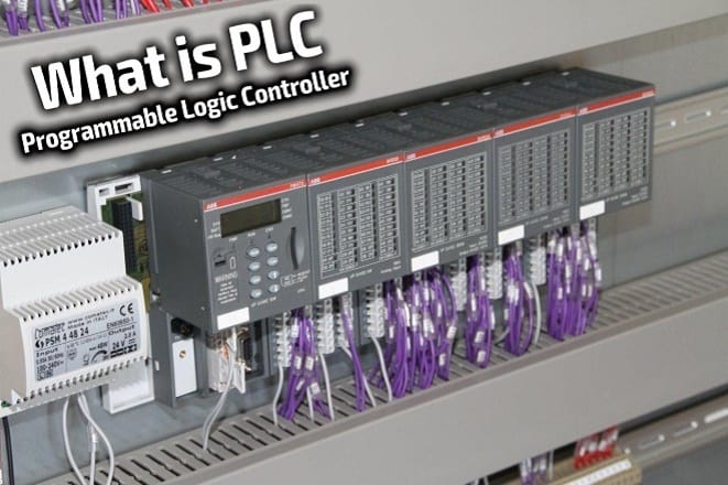
Image disclaimer: For identification and illustration only. It may show a product by another manufacturer and may not depict the exact item described; it is not a statement of any product’s quality, approval or performance. Third-party image and trademark rights belong to their owners. See full notice.
What Is It?
A Programmable Logic Controller (PLC) is a rugged industrial computer designed for real‑time control of electromechanical processes. In AGL applications, the PLC serves as the central automation engine that monitors input signals (e.g., CCR status, switch positions, sensor data) and executes programmed logic to control outputs (e.g., brightness steps, circuit switching, alarm annunciation). PLCs are distinguished by their deterministic scan cycle, high reliability, wide operating temperature range, and resistance to electrical noise and vibration. They are the backbone of modern Airfield Lighting Control and Monitoring Systems (ALCMS), providing the link between operator commands and the physical AGL infrastructure.
Purpose & Function
The PLC exists to translate an operator's high-level command — switch to CAT III lighting configuration, raise runway edge lights to full intensity — into the exact sequence of low-level actions that make it happen safely and correctly across potentially hundreds of circuits and devices, every single time, without the timing errors or inconsistency a manual process would introduce. Its deterministic scan cycle is what guarantees that a given input reliably produces the same output within a predictable time window, which matters enormously when a lighting change needs to happen in coordination with an approaching aircraft.
Because this component sits between operator intent and the physical infrastructure itself, its ruggedness and reliability requirements are especially strict: a PLC that fails or behaves unpredictably doesn't just lose data, it can leave lighting in an unintended state during live operations, which is why industrial-grade construction and resistance to electrical noise and vibration are treated as safety requirements rather than convenience features.
Where Is It Used?
PLCs are deployed throughout the AGL control infrastructure, including:
- CCR Control Rooms: Central PLC racks managing multiple CCRs, brightness control, and circuit switching.
- Remote Substations: Distributed PLCs controlling local lighting circuits and reporting status back to the main ALCMS.
- Runway & Taxiway Lighting Control: Managing power distribution, step switching, and fault detection for each lighting circuit.
- Approach Lighting Systems: Controlling sequenced flashing lights, barrettes, and intensity levels.
- PAPI & Visual Aids: Managing power and monitoring lamp failures in glide slope indicators.
- Obstruction Lighting: Controlling beacon patterns and monitoring lamp/LED status.
- RWSL (Runway Status Light) Systems: Processing surveillance data and controlling stop bars, runway guard lights, and take‑off hold lights.
- SCADA Integration: Acting as the interface between the AGL system and higher‑level airport SCADA or building management systems.
Installation & Location
The PLC rack mounts on a DIN rail inside the CCR control room cabinet or the remote substation enclosure it controls, positioned with clear access to its I/O terminal strips for field wiring and maintenance. Field wiring (CCR control/feedback, Remote I/O links, sensor inputs) terminates on the rack's own terminal blocks rather than being spliced elsewhere, keeping fault-finding straightforward; power is fed from the cabinet's UPS-backed DC supply, and the network-side connection to the ALCMS runs on structured Ethernet cabling separate from the field-side wiring. Remote substation PLCs are sited close to the CCRs and lighting circuits they manage so field cable runs stay short, reporting status back to the central ALCMS server over the fibre backbone rather than a direct copper run.
How Does It Work?
The PLC operates on a continuous scan cycle, executing the control program repeatedly. Key functional aspects include:
- Input Scan: The PLC reads all input signals (digital: switch states, alarm contacts; analog: current/voltage levels, temperature) from field devices via I/O modules.
- Program Execution: The user‑defined control program (ladder logic, structured text, or function block diagram) processes the input data, applies logical and mathematical operations, and determines the required output states.
- Output Update: The PLC writes the calculated output states to the output modules, which then actuate contactors, relays, CCR setpoints, or communication messages.
- Communication: PLCs communicate with the ALCMS, remote I/O, and other controllers via industrial protocols (Modbus, Profibus, Ethernet/IP, OPC UA) to exchange status, commands, and diagnostic data.
- Fault Detection: The PLC continuously monitors for abnormal conditions (overcurrent, open circuit, communication loss) and triggers alarms or automatic remedial actions.
- Redundancy: Critical AGL applications often use redundant PLC configurations (dual hot‑standby) to ensure zero downtime in case of a controller failure.
PLCs are programmed using vendor‑specific software (e.g., Siemens TIA Portal, Rockwell Studio 5000, Schneider EcoStruxure) and are designed for long service life (15‑20 years) with minimal maintenance.
System Architecture & Control Logic
The PLC sits one level below the ALCMS server and one level above the CCRs, Remote I/O, and field devices it directly controls, and it is where the actual switching and setpoint decisions for its assigned circuits are made. Commands arrive from the ALCMS server over the Ethernet backbone (Modbus TCP, Profinet, or OPC UA) — a brightness-step change, a circuit on/off instruction, a pre-set lighting configuration — and the PLC translates each into the specific outputs its own I/O and control program require, whether that means writing a setpoint to a CCR, energising a contactor, or issuing a command over a fieldbus to a Remote I/O unit further out. It executes that logic locally and continuously on its own scan cycle regardless of network conditions, so lighting control keeps functioning if the link to the ALCMS server is temporarily lost; it also continuously reports the resulting status and any fault conditions back upstream, and dual hot-standby PLCs are typically used for the circuits where a controller failure cannot be tolerated.
ALCMS Server
Issues validated commands over Modbus TCP / Profinet / OPC UA
PLC
Local control program — runs its scan cycle independent of network state
CCRs / Remote I/O / Field Devices
Contactors, setpoints & fieldbus commands to the actual circuits
The PLC Scan Cycle
Input Scan
Reads digital & analog signals from field devices via I/O modules
Program Execution
Ladder logic / ST / FBD processes inputs, applies control logic
Output Update
Contactors, relays & CCR setpoints actuated
Communication
Status, commands & diagnostics exchanged with ALCMS / Remote I/O
Fault Detection
Overcurrent, open circuit & comms loss trigger alarms
Physical Construction
The PLC is built as a modular rack system: a base CPU module carrying the processor, memory, and communication ports clips onto a DIN rail alongside expansion I/O modules, each connected through a backplane bus connector so the system can be extended without rewiring. The housing is an extruded-aluminium or high-impact plastic shell with a conformally coated internal board to resist dust, humidity, and vibration in an unconditioned equipment room or field cabinet. Removable, colour-coded terminal blocks on each I/O module allow field wiring to be disconnected without removing the module itself, simplifying maintenance and module replacement. Where a field-mount rating is required rather than panel-mount, the entire rack assembly is enclosed in a sealed IP65 cabinet with cable glands for each conductor entry, and a lithium battery module clips onto the CPU board to retain the program and real-time clock through a power loss.
Technical Parameters
| Parameter | Typical Value |
|---|---|
| Processor | 32‑bit ARM or x86, 100 MHz – 1.5 GHz |
| Memory (Program) | 128 KB – 32 MB (Flash / RAM) |
| I/O Capacity | Up to 1024 digital I/O, 256 analog I/O (expandable) |
| Scan Cycle Time | 1 – 100 ms (deterministic) |
| Communication Protocols | Modbus TCP/RTU, Profibus, Profinet, Ethernet/IP, OPC UA, BACnet |
| Redundancy | Hot‑standby (optional), bumpless transfer |
| Operating Temperature | -25°C to +60°C (industrial grade) |
| Storage Temperature | -40°C to +85°C |
| Humidity | 5% – 95% RH (non‑condensing) |
| Protection Class | IP20 (panel‑mount), IP65 (field‑mount) |
| Power Supply | 24 VDC, 120 VAC, or 230 VAC |
| Battery Backup | Lithium battery for program retention (5‑10 years) |
| Diagnostics | Integrated LEDs, web server, or HMI interface |
| Certifications | UL, CE, IEC 61131‑2 (industrial control equipment) |
Electrical Requirements
| Requirement | Typical Value |
|---|---|
| Circuit Position | Control-cabinet mounted, standalone powered controller |
| Power Supply | 24 VDC, 120 VAC, or 230 VAC |
| Isolation | I/O modules typically opto-isolated from field wiring |
| Earthing | Chassis/DIN rail bonded to cabinet earth |
| Fault Protection | Internal fusing; output modules rated per connected load |
Applicable Standards
IEC 61131‑2
Programmable controllers — equipment requirements and tests
IEC 61131‑3
Programming languages for PLCs (Ladder, ST, FBD, SFC, IL)
IEC 61822
Performance requirements for the Constant Current Regulators (CCRs) this PLC commands and monitors
FAA AC 150/5345‑56
Specification for AGL control and monitoring equipment
Installation Requirements
DIN-Rail Mounting & I/O Access
MechanicalMount the PLC rack on a DIN rail inside the CCR control room cabinet or remote substation enclosure, positioned with clear access to its I/O terminal strips for field wiring and maintenance.
Field Wiring Termination
ElectricalTerminate CCR control/feedback, Remote I/O links, and sensor inputs on the rack's own terminal blocks rather than splicing elsewhere, keeping fault-finding straightforward.
UPS-Backed Power Feed
ElectricalFeed power from the cabinet's UPS-backed DC supply, confirming voltage and loading before field wiring is energised.
Segregated Network Connection
ElectricalRun the network-side connection to the ALCMS on structured Ethernet cabling, kept separate from the field-side wiring terminated on the rack.
Logic Program Load & Verification
DocumentationLoad and verify the control logic program against the design before the PLC is brought into service, confirming I/O mapping matches the field wiring as-built.
Pre-Commissioning Sign-off
DocumentationRecord rack position, field wiring terminations, and power feed as-built before commissioning testing begins.
Testing & Commissioning
Power Supply & Backup Battery Check
Pre-CommissioningConfirm the PLC and its backup battery operate correctly before the field I/O is connected.
I/O Module Point-to-Point Test
CommissioningVerify every input and output point against its field device, confirming correct wiring and addressing.
Communication Link Test
CommissioningConfirm the PLC establishes and holds communication with the ALCMS server and any networked field devices.
Logic & Sequence Validation
Pre-CommissioningRun the programmed control logic through scripted test scenarios and confirm outputs respond correctly.
Fail-Safe & Alarm Response Test
CommissioningSimulate fault conditions and confirm the PLC drives outputs to a safe state and raises the correct alarms.
Enclosure Thermal Check
Pre-CommissioningConfirm the PLC operates within its rated temperature range inside its installed enclosure.
Firmware & Program Version Verification
Pre-CommissioningConfirm the installed firmware and control program match the approved commissioning revision.
Documentation & As-Built Sign-off
Final AcceptanceRecord I/O test results, logic validation, and program version in the commissioning dossier for handover.
Inspection & Maintenance
Power Supply Check
AnnualVerify power input stability and inspect the supply unit for signs of stress or capacitor ageing.
Communication Link Test
Semi-annualTest communication links to upstream and downstream devices to catch developing interruptions early.
I/O Module Diagnostic Check
AnnualRun diagnostics on I/O modules to identify degraded channels before they cause a field fault.
Battery Replacement Check
AnnualCheck backup battery status and replace proactively to prevent loss of retained memory or clock settings.
Firmware & Software Review
AnnualReview firmware and program versions against baseline and apply vendor updates addressing known bugs.
Enclosure Thermal Check
Semi-annualConfirm enclosure ventilation or cooling is adequate to prevent sustained overheating.
Common Field Issues
Power Supply Fluctuation
PLCs are sensitive to power supply quality. Voltage dips or spikes from the airfield electrical network can cause processor resets or I/O faults. Use of UPS and line conditioners is recommended to ensure stable operation.
Communication Interruption
Fiber optic or Ethernet cables can be damaged during construction or maintenance. Regular inspection of communication paths and use of redundant networks (ring topology) can prevent loss of control.
I/O Module Failure
Relay output modules have a finite contact life; solid‑state outputs can fail due to overcurrent or transient voltages. Regular replacement of output modules (every 5‑10 years) and proper surge protection are essential.
Battery Failure
The lithium battery that retains the program and real‑time clock can fail, causing loss of program or time‑stamped alarms. Replace batteries proactively every 5 years per manufacturer recommendations.
Firmware/Software Bugs
PLC firmware or control program logic errors can cause unexpected behaviour. Rigorous testing (including simulation and factory acceptance testing) and proper version control are critical.
Overheating in Enclosures
PLCs generate heat; inadequate ventilation or failed cooling fans in control cabinets can cause overheating, reducing processor speed or causing shutdown. Ensure proper enclosure sizing and cooling.
Troubleshooting Guide
Processor Resets or I/O Faults Without Obvious Cause
Loss of Control or Communication to Field Equipment
Specific Output Fails to Energise or Behaves Erratically
PLC Program or Time-Stamped Alarms Lost After a Power Outage
Unexpected System Behaviour Following a Program or Firmware Change
Reduced Processor Performance or Unexpected Shutdown
Failure Modes & Root Causes
Power Quality Disturbance
Communication Path Damage
I/O Module End-of-Life Failure
Retention Battery Failure
Program / Firmware Regression
Cabinet Overheating
Safety & Operational Notes
Electrical Isolation Before Cabinet Entry
Electrical SafetyDe-energise and lock out the cabinet's incoming supply before working inside on the PLC, its I/O wiring, or power supply, and verify zero energy before touching any terminal.
Change Control Before Program Changes
OperationalApply program or firmware changes through a documented change-control process with a tested rollback plan, since a faulty logic change can affect every circuit the PLC controls.
Data-Loss Precaution Before Battery Replacement
OperationalBack up the program and retained data before replacing the PLC's retention battery, since some controllers lose retained memory if power and battery backup are both interrupted.
ESD Precautions When Handling Modules
MechanicalUse an anti-static wrist strap and follow ESD-safe handling procedures when removing or installing I/O modules or processor cards, since static discharge can damage sensitive electronics.
Cabinet Cooling / Ventilation Maintained
OperationalKeep cabinet fans, filters, and vents clear of dust and obstruction, since PLC processors and power supplies are sensitive to the sustained overheating a blocked cabinet can cause.
Engineering & Expert Notes
Scan Cycle Budget Determines Real Response Time
PerformanceEvery I/O card, communication block, and rung of logic added over the life of a system adds to the scan cycle, and a PLC that responded instantly when commissioned can develop a perceptible lag in brightness-step changes years later once the program has grown. Budget spare scan-time headroom at design, not just spare I/O points.
Keep Redundant PLCs on Identical Firmware and Program Versions
ReliabilityA mismatch between the primary and standby controller's firmware or program revision is one of the most common causes of a failed or erratic failover; version-lock both units and log every change to each so a discrepancy is caught before it's needed under fault conditions.
Tune the Watchdog Timer to the Process, Not a Default Value
ConfigurationA watchdog set too short trips on legitimate scan-time variation and forces nuisance shutdowns; set too long, it delays detection of a genuinely hung controller. Base the setting on measured worst-case scan time with margin, not the factory default carried over from commissioning.
Isolate I/O Modules From CCR Switching Transients
ElectricalThe switching transients generated when a CCR steps brightness or a contactor changes state can couple into nearby I/O wiring and cause spurious input changes. Route and shield I/O cabling away from power switching runs, and confirm surge protection is in place on card inputs monitoring CCR status.
Track Battery-Backed Memory Separately From the Maintenance Calendar
MaintenanceThe battery holding the real-time clock and retentive memory has its own end-of-life independent of the rest of the controller, and its failure can silently corrupt stored setpoints or reset the clock on next power loss. Track its replacement interval as its own line item rather than assuming it's covered by general PLC servicing.
Document Forced I/O Before Leaving the Cabinet
TroubleshootingA forced input or output left engaged after field troubleshooting can mask a real fault indefinitely, since the controller no longer sees the true field state. Log every force applied during diagnostics with a removal step, and check for outstanding forces as a standard item before closing out any PLC work.
Frequently Asked Questions
Short answers about the PLC: what it is, how it works, typical specifications, standards, maintenance and common faults.
Q1What is a PLC?
A Programmable Logic Controller (PLC) is a rugged industrial computer designed for real‑time control of electromechanical processes. In AGL applications, the PLC serves as the central automation engine that monitors input signals (e.g., CCR status, switch positions, sensor data) and executes programmed logic to control outputs (e.g., brightness steps, circuit switching, alarm annunciation). PLCs are distinguished by their deterministic scan cycle, high reliability, wide operating temperature range, and resistance to electrical noise and vibration. They are the backbone of modern Airfield Lighting Control and Monitoring Systems (ALCMS), providing the link between operator commands and the physical AGL infrastructure.
Q2What is the purpose of a PLC?
The PLC exists to translate an operator's high-level command — switch to CAT III lighting configuration, raise runway edge lights to full intensity — into the exact sequence of low-level actions that make it happen safely and correctly across potentially hundreds of circuits and devices, every single time, without the timing errors or inconsistency a manual process would introduce.
Q3Where is a PLC used and installed?
PLCs are deployed throughout the AGL control infrastructure, including: CCR Control Rooms: Central PLC racks managing multiple CCRs, brightness control, and circuit switching. Remote Substations: Distributed PLCs controlling local lighting circuits and reporting status back to the main ALCMS. Runway & Taxiway Lighting Control: Managing power distribution, step switching, and fault detection for each lighting circuit. Approach Lighting Systems: Controlling sequenced flashing lights, barrettes, and intensity levels. PAPI & Visual Aids: Managing power and monitoring lamp failures in glide slope indicators.
Q4How does a PLC work?
The PLC operates on a continuous scan cycle, executing the control program repeatedly. Key functional aspects include: Input Scan: The PLC reads all input signals (digital: switch states, alarm contacts; analog: current/voltage levels, temperature) from field devices via I/O modules. Program Execution: The user‑defined control program (ladder logic, structured text, or function block diagram) processes the input data, applies logical and mathematical operations, and determines the required output states.
Q5What are the typical technical parameters of a PLC?
Typical values are — Processor: 32‑bit ARM or x86, 100 MHz – 1.5 GHz; Memory (Program): 128 KB – 32 MB (Flash / RAM); I/O Capacity: Up to 1024 digital I/O, 256 analog I/O (expandable); Scan Cycle Time: 1 – 100 ms (deterministic); Communication Protocols: Modbus TCP/RTU, Profibus, Profinet, Ethernet/IP, OPC UA, BACnet; Redundancy: Hot‑standby (optional), bumpless transfer; Operating Temperature: -25°C to +60°C (industrial grade); Storage Temperature: -40°C to +85°C; Humidity: 5% – 95% RH (non‑condensing); Protection Class: IP20 (panel‑mount), IP65 (field‑mount); Power Supply: 24 VDC, 120 VAC, or 230 VAC.
Q6What are the electrical requirements for a PLC?
Typical requirements are — Circuit Position: Control-cabinet mounted, standalone powered controller; Power Supply: 24 VDC, 120 VAC, or 230 VAC; Isolation: I/O modules typically opto-isolated from field wiring; Earthing: Chassis/DIN rail bonded to cabinet earth; Fault Protection: Internal fusing; output modules rated per connected load.
Q7Which standards apply to a PLC?
The main references are IEC 61131‑2 — Programmable controllers — equipment requirements and tests; IEC 61131‑3 — Programming languages for PLCs (Ladder, ST, FBD, SFC, IL); IEC 61822 — Performance requirements for the Constant Current Regulators (CCRs) this PLC commands and monitors; FAA AC 150/5345‑56 — Specification for AGL control and monitoring equipment. Always verify the current edition and your aerodrome's approved requirements.
Q8How often should a PLC be inspected and maintained?
Typical maintenance tasks and intervals are: Power Supply Check (annual); Communication Link Test (semi-annual); I/O Module Diagnostic Check (annual); Battery Replacement Check (annual); Firmware & Software Review (annual); Enclosure Thermal Check (semi-annual). Your airport's approved maintenance programme takes precedence.
Q9How do I troubleshoot common PLC faults?
Common symptoms covered are: Processor Resets or I/O Faults Without Obvious Cause; Loss of Control or Communication to Field Equipment; Specific Output Fails to Energise or Behaves Erratically; PLC Program or Time-Stamped Alarms Lost After a Power Outage; Unexpected System Behaviour Following a Program or Firmware Change; Reduced Processor Performance or Unexpected Shutdown. For example, for "Processor Resets or I/O Faults Without Obvious Cause": Likely Cause: A voltage dip or spike from the airfield electrical network has reset the processor or tripped an I/O fault, particularly if the PLC isn't protected by UPS and line conditioning. Diagnostic Steps: Check power quality logs or event timestamps against known electrical disturbances on the airfield network; verify UPS and line conditioner status if fitted. Corrective Action: Install or repair UPS and line conditioning if not already protecting the PLC; document the event and monitor for recurrence to confirm the fix.
Related Components
Go Beyond the Component. Understand the Complete AGL System.
You have explored the component. Now understand how it works within the complete Airfield Ground Lighting system.
Learn AGL from fundamentals to design, installation, testing, photometry, commissioning, maintenance and troubleshooting through structured technical training at Precision AGL Academy.
Build practical knowledge. Understand the circuit. Read the standards. Troubleshoot with confidence.
Your next step in AGL starts here.
Need expert guidance on PLC selection, programming, or integration for your AGL system?
Precision AGL Academy provides advice on hardware selection, redundancy strategies, communication protocols, and field commissioning.
Follow the Academy
Important Notice, Disclaimer & Limitation of Liability
Please read before relying on any content on this page.
- Purpose and intended users. This page on Programmable Logic Controller (PLC) is an independent educational and informational reference for competent, suitably trained and authorised airfield ground lighting (AGL) and aerodrome electrical personnel. It is not professional engineering, legal or regulatory advice, and using it does not create any professional or client relationship.
- Safety. Work on series circuits, constant current regulators (CCRs), isolating transformers, cables, connectors and lighting equipment can be fatal. Always apply the aerodrome’s permit-to-work and isolation/LOTO procedures, prove dead, use correctly rated instruments and PPE, and follow the manufacturer’s instructions. Nothing here authorises work on live equipment or the bypassing of any safety device or interlock.
- Aviation operations. Nothing here authorises installation, modification, energisation, adjustment, return to service, a change of operating category (CAT I/II/III), a NOTAM or any aerodrome certification or approval decision. These rest with the aerodrome operator, the air navigation service provider and the competent regulator.
- Specifications, ratings and typical values. Descriptions, parameters, ratings, dimensions, photometric values, wattages, service lives, maintenance tasks and intervals, failure modes, certifications (for example CE, FCC, UL or IEC marks) and part or type designations are general, typical and indicative. They may not match any particular product, make, model or version, and they are not a datasheet, design, specification, selection, sizing, procurement or acceptance criterion. The manufacturer’s current documents, the approved design and the project specification prevail.
- Standards and regulations. References to ICAO, FAA, IEC, IEEE, ISO, BIS, DGCA and other standards are paraphrased summaries for orientation only. They may be incomplete or out of date, and standards are revised from time to time. Consult the current official editions. Following this content does not guarantee compliance with any law, standard or regulatory approval, and the regulator’s requirements always prevail.
- No warranty. Content is provided “as is” and “as available”, without warranty of any kind, express or implied, including accuracy, completeness, currency or fitness for a particular purpose. Real installations differ in design, equipment make and model, age and condition.
- Limitation of liability. To the fullest extent permitted by applicable law, Precision AGL Academy, Precision AGL Solutions and their owners, authors and contributors are not liable for any injury, death, loss, damage, downtime, penalty or regulatory consequence, whether direct or indirect, arising from the use of, reliance on, or inability to use this content. Nothing in this notice excludes or limits any liability that cannot lawfully be excluded or limited.
- Independence, brands and no endorsement. This is an independent publication. It is not affiliated with, sponsored by or endorsed by ICAO, the FAA, the IEC, DGCA, AAI, any airport, regulator, supplier or equipment manufacturer. Third-party names, product designations, standard designations and trademarks (including Megger®, Siemens, Eaton, Crouse-Hinds, ADB SAFEGATE, Fluke, ABB and Honeywell) belong to their respective owners and are used only for identification and description. Mention of a brand, product or supplier is not a recommendation, and we do not sell, supply or quote for any component described.
- Images and third-party content. Images and illustrations are shown to help identify the type of component. They may show products of various manufacturers, may not depict the exact item described, and are not a statement about any product’s quality, approval or performance. Copyright and trademarks in third-party images, logos and photographs belong to their respective owners and are not claimed as ours. If you are a rights holder and want an image removed, replaced or credited, email precisionaglsolutions@gmail.com with the page address and we will act promptly.
- Training and services. Mentions of training, courses, consultation, advice, selection, installation, calibration or other support, including the “Learn…Certify” pathway, describe learning stages and are not an offer, quotation, tender or promise of any result. Contacting us or our replying creates no engagement or duty of care; an engagement exists only under a written agreement. We are not a regulator or certification body, and completing any course or reading this content is not a certification, accreditation or authorisation to work on any aerodrome.
- Copyright, privacy and corrections. © 2026 Precision AGL Academy. All rights reserved. Text, structure, compilations and diagrams may be viewed for personal reference and internal training only; any other copying, republication or commercial use needs our written permission. If you email, telephone or message us, we use your details only to respond and handle your matter, in line with applicable Indian law including the Digital Personal Data Protection Act, 2023; please do not send confidential or security-sensitive information. To display this page your browser requests fonts, icons and images from third-party servers, which receive your IP address and browser details under their own policies. Content is reviewed periodically with no obligation to update. To report an error, safety concern or rights issue, write to precisionaglsolutions@gmail.com.