Transmission Tower Light
A specialized aviation obstruction light for high-voltage transmission towers and power line structures, featuring medium-intensity red lights at multiple levels to delineate tower height. Engineered to withstand extreme weather, corona discharge, and electromagnetic interference while providing reliable 24/7 obstruction marking for power grid infrastructure.
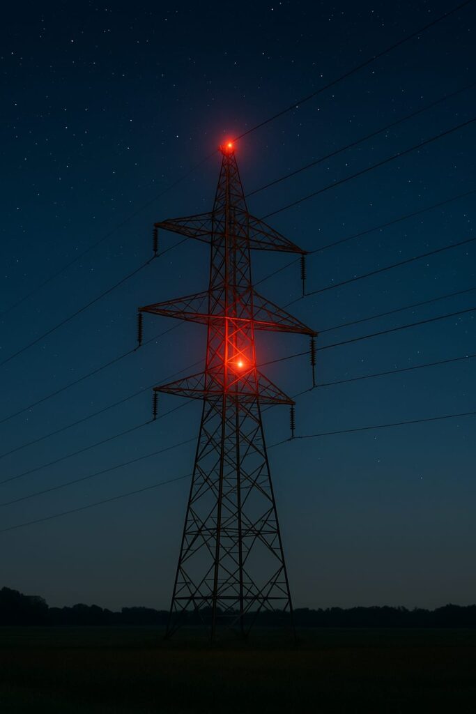
Image disclaimer: For identification and illustration only. It may show a product by another manufacturer and may not depict the exact item described; it is not a statement of any product’s quality, approval or performance. Third-party image and trademark rights belong to their owners. See full notice.
What Is It?
A Transmission Tower Light is an aviation warning light system installed on high-voltage electrical transmission towers to alert aircraft of their presence. These lattice steel structures often exceed 50–100 metres in height and are located in vast corridors that can cross flight paths. The lighting system typically uses medium‑intensity red steady‑burning or flashing lights installed at the tower's top and at intermediate levels (every 45 metres) to clearly indicate the structure's height and shape. The lights are designed to operate reliably in the presence of strong electromagnetic fields, corona discharge, and severe weather, with robust surge protection and non‑corrosive materials.
Purpose & Function
Transmission tower lighting exists because these structures are often strung across long corridors far from any airport, in locations where a pilot has no other reason to expect a tall obstacle and no surrounding urban lighting context to draw attention to it, unlike a building obstruction light situated in a lit city skyline. Marking both the tower top and intermediate levels serves the same purpose as on any tall structure — conveying the true height and shape rather than just the summit — but here it's applied to a lattice steel structure whose thin profile can otherwise be genuinely difficult to see against open sky or terrain even in daylight. The lighting's engineering emphasis on withstanding electromagnetic interference, corona discharge, and surge events exists because this is the one obstruction-light category installed directly on energized high-voltage infrastructure, where a lighting failure caused by the tower's own electrical environment would defeat the very purpose the light is there to serve.
Where Is It Used?
Installed on high‑voltage transmission towers (typically 110kV to 765kV and above) that exceed 45 metres (150 feet) AGL or are located near aerodromes or aviation corridors. Used extensively across power grids worldwide. Multiple lights are installed at the top and at intermediate levels (every 45 metres) on very tall towers to provide a clear outline. The lights must be visible from all directions, requiring omnidirectional or 360° coverage with specific beam patterns. Special attention is given to mounting hardware that does not compromise the tower's structural integrity or insulation properties.
Installation & Location
Fixtures are installed at the tower top and at intermediate levels at the specified vertical spacing, mounted on brackets that hold the light well clear of energized conductors, insulators, and hardware, with clearances set to the tower's electrical design rather than to lighting convenience alone. Mounting hardware and cabling are specified for the electromagnetic field strength and corona discharge present on energized towers, with surge protection, shielding, and bonding integrated so the lighting circuit is isolated from the tower's high-voltage system. Access for installation and maintenance follows the utility's live-line or de-energized work procedures, since these fixtures sit on active electrical infrastructure rather than a passive structure. Power is typically taken from a low-voltage supply run alongside the tower rather than tapped from the transmission conductors themselves, with cabling routed to avoid any point where lighting and high-voltage circuits could interact.
How Does It Work?
Each transmission tower light is powered either from the tower's own power supply (via a dedicated distribution transformer) or from an independent solar‑powered system with battery backup. The light source is typically an LED array with a red filter, providing medium intensity (~2,000 cd) for nighttime and low‑visibility conditions. Some installations use flashing lights (20–40 fpm) for enhanced visibility. The lights are controlled by an integral photocell or a remote monitoring system. The housing is constructed from non‑corrosive materials (marine‑grade aluminium or stainless steel) with IP66/IP67 protection, and features heavy‑duty surge protection to withstand lightning strikes and switching surges. Special EMI shielding prevents interference with the tower's control systems.
System Architecture & Control Logic
Each tower light operates as a self-contained switching unit rather than a fixture on a shared circuit: the photocell integral to the fixture (or a remote monitoring interface) reads ambient light level directly at the tower and switches the LED array on at dusk and off at dawn without any external scheduling command. Where flashing operation is specified, an internal flash controller sets the 20–40 fpm rate locally at each light — there is no synchronising signal between lights on the same tower or between towers, since obstruction lighting on a static structure does not require the fleet-wide flash coordination used on wind farms or airfield circuits. Power reaches the fixture either from the tower's own distribution transformer on grid-tied installations, or from a dedicated solar panel and battery bank where an independent supply is used, with surge protection and EMI shielding isolating the light's switching circuit from the high-voltage environment of the structure it is mounted on. Fault reporting runs through the remote monitoring interface: each light, or a light group, reports operating status — on/off state, lamp current, and battery state of charge for solar units — back to a central monitoring system or the utility's SCADA network, so a failed unit at height is flagged without requiring a visual inspection climb.
Power Source → Photocell → Flash Controller (per fixture) → Protected LED Array → Remote Monitoring / SCADA
Structure Elevation & Power Path
Additional lights repeat every 45m up the lattice structure to outline its full height
Physical Construction
The lantern head is built around a die-cast aluminium housing, anodised or powder-coated for corrosion resistance and shielded internally to protect the driver electronics from the strong electromagnetic fields and corona discharge present near high-voltage conductors. The red LED array sits behind a moulded polycarbonate dome lens with internal prismatic ribbing to spread light evenly across the full 360° horizontal arc, gasket-sealed to the housing to achieve an IP66/IP67 rating against wind-driven rain and dust. The housing mounts to the lattice steel tower via a galvanised steel bracket or crossarm fitting, bolted directly to the tower structure and bonded to its earthing and lightning-protection system; units at intermediate levels use standardised clamp fittings so they can be positioned at the required 45-metre intervals along the tower's height. Internal driver electronics are potted or conformal-coated and isolated in a shielded compartment away from the optical chamber to further reduce susceptibility to induced currents, with cabling routed through EMI-filtered, surge-protected glands. All external hardware, brackets, and fasteners are stainless steel or hot-dip galvanised, and where the tower lacks mains supply the fixture may instead draw from a dedicated solar panel and battery assembly mounted on the structure.
Technical Parameters
| Parameter | Typical Value |
|---|---|
| Light Source | LED array (red) – medium intensity |
| Colour | Aviation Red (steady or flashing) |
| Intensity (Night) | ~2,000 cd (steady or 20–40 fpm flash) |
| Flash Pattern | 20–40 flashes per minute (optional) |
| Mounting Height | Top of tower, plus intermediate levels (every 45m) |
| Beam Coverage | Omnidirectional (360° horizontal) |
| EMI/Corona Protection | Shielded electronics, non‑corrosive housing |
| Protection Class | IP66 / IP67, lightning‑protected |
| Power Supply | 230V AC (tower supply) or solar + battery |
Electrical Requirements
| Requirement | Typical Value |
|---|---|
| Circuit Type | Dedicated mains-fed circuit from the tower supply, or solar + battery where mains is unavailable |
| Supply Voltage | 230V AC (tower supply) or solar panel with battery storage |
| Cable Type | EMI/corona-shielded cable, routed and bonded to avoid interaction with the tower's high-voltage conductors |
| Control Input | Photocell or timer switching for dusk-to-dawn/steady operation |
| Insulation Resistance | ≥ 50 MΩ (megger test, cable-to-ground) |
| Earthing/Grounding | Fixture body bonded to the tower's own earthing and lightning protection system, coordinated to avoid a ground loop with the HV structure |
| Fault Protection | Shielded electronics protect against EMI/corona interference; lamp/LED failure detection at the local isolator |
Photometric Requirements
| Parameter | Typical Value |
|---|---|
| Luminous Intensity | 2,000 – 20,000 cd (medium intensity, day/night dependent) per ICAO Annex 14 / FAA AC 70/7460-1 |
| Flash Rate (where flashing) | 20–40 flashes per minute |
| Beam Pattern | Omnidirectional (360° horizontal coverage) around the tower structure |
| Vertical Beam Spread | Sufficient vertical spread to remain visible from typical approach descent angles |
| Chromaticity | Aviation Red within ICAO Annex 14 colour boundary |
| Day/Night Intensity Switching | Photocell/timer-selected reduced night intensity |
| EMI/Corona Immunity | Optical output and control electronics unaffected by proximity to high-voltage conductors |
| Test Method | Photometric verification at commissioning, with periodic intensity checks |
Applicable Standards
ICAO Annex 14
Obstruction lighting for transmission towers
FAA AC 70/7460-1
Obstruction marking and lighting for tall structures
FAA AC 150/5345-43
Specification for obstruction lighting equipment (electrical/photometric performance)
IEC 62305
Protection against lightning, applied to the tower's lighting and bonding system
Installation Requirements
Intermediate-Level Positioning
CivilConfirm top-of-tower and intermediate-level lights are positioned at the design 45-metre intervals using standardised clamp fittings, so the tower's full height is traced for approaching aircraft.
Bracket/Crossarm Fixing
MechanicalBolt the galvanised steel bracket or crossarm fitting directly to the lattice steel tower structure per the fixing schedule.
Earthing & Lightning Bonding
ElectricalBond the fixture housing to the tower's earthing and lightning-protection system, since proximity to high-voltage conductors makes this connection critical for equipment survival.
EMI-Filtered Gland Termination
ElectricalRoute and terminate cabling through the EMI-filtered, surge-protected glands as designed, keeping the driver electronics compartment shielded from induced currents near the conductors.
Supply Source Confirmation
ElectricalConfirm whether the fixture draws from the tower's mains supply or a dedicated solar panel and battery assembly, and terminate that source before energisation.
Dome Seal Check
MechanicalConfirm the gasket seal between the lens dome and housing seats correctly to achieve the rated IP66/IP67 protection before commissioning.
Pre-Energisation Sign-off
DocumentationRecord fixture positions, bonding, and cable termination as-built before the tower is signed off and climbing access is closed out.
Testing & Commissioning
Insulation Resistance Test
Pre-EnergisationMegger-test the supply cable and distribution transformer (or solar-battery circuit) before energisation, confirming insulation resistance clears the acceptable minimum given the high-voltage environment.
EMI Shielding & Surge Protection Verification
Pre-EnergisationConfirm the fixture's EMI shielding and surge protection are correctly fitted and bonded before energisation, given the strong electromagnetic fields and corona discharge near energised conductors.
Photocell Threshold Calibration
EnergisationCalibrate the integral photocell's day/night switching threshold against a reference light meter so the fixture switches on at dusk and off at dawn.
Photometric Intensity Test
Final AcceptanceMeasure light output at the tower top and each intermediate level with a calibrated photometer against ICAO/FAA medium-intensity thresholds (~2,000 cd).
Intermediate-Level Coverage Verification
Final AcceptanceConfirm every intermediate-level light at the specified ~45m spacing is present and correctly outlines the tower's full lattice height.
Grid-Tied / Solar Power Path Verification
Final AcceptanceConfirm the fixture draws correctly from its distribution transformer tap-off or, where independent, from the solar panel and battery backup, with clearances maintained from energised conductors and hardware.
Documentation & As-Built Sign-off
Final AcceptanceRecord insulation, shielding, threshold calibration, and photometric readings alongside as-built level positions in the commissioning dossier for handover.
Inspection & Maintenance
Grounding & Surge Arrester Check
AnnualTest grounding continuity and inspect surge arresters, since transmission towers are frequent lightning targets and repeated surges can damage the light's power supply.
Insulator & Shielding Inspection
AnnualCheck insulators and shielded cabling for wear that could let corona discharge interfere with the light's electronics or generate RF noise.
Mounting Bolt Torque Check
AnnualRe-torque mounting bracket bolts to spec, since wind-induced vibration and conductor galloping can fatigue hardware over time.
Photometric Intensity Check
AnnualVerify beam intensity and colour against applicable obstruction lighting thresholds using a calibrated photometer.
Lens & Housing Cleaning
Semi-annualClean the lens and housing of dust, pollution deposits, and bird debris to maintain full light output.
Vibration Damping Mount Check
AnnualInspect vibration-damping mounts for wear or compression set that could let structural vibration transmit into the fixture.
Common Field Issues
Corona Discharge Interference
High‑voltage fields can cause corona discharge, which may interfere with the light's electronics and create radio frequency noise. Using shielded cables and EMI‑hardened components is essential. Regular inspection of insulators and grounding is required.
Lightning and Switching Surges
Transmission towers are frequent lightning targets. Surge protection devices and proper grounding are critical. Repeated surges can damage the light's power supply and control electronics. Use of heavy‑duty surge arresters is mandatory.
Structural Vibration and Fatigue
Towers experience wind‑induced vibration and conductor galloping, which can cause mechanical fatigue in mounting brackets. Use of vibration‑damping mounts and regular bolt torque checks is recommended.
Troubleshooting Guide
Light Completely Dark — Grid-Tied Unit
Light Completely Dark — Solar-Powered Unit
Light Fails to Switch On at Dusk or Off at Dawn
Erratic Flash Rate
Radio Frequency Noise or Electronics Malfunction Near Energised Conductors
Repeated Surge-Related Failures
Failure Modes & Root Causes
Distribution Transformer Feed Failure (Grid-Tied)
Battery Bank / Charge Controller Failure (Solar)
Corona-Induced Electronics Damage
Surge Arrester Degradation
Flash Controller Timing Fault
Safety & Operational Notes
High-Voltage Line Permit
Electrical SafetyNever climb or work on a transmission tower without the utility's own permit-to-work and confirmation that the adjacent conductors are de-energised or that safe clearance distances are being maintained.
Induced Voltage / EMF
Electrical SafetyBe aware that even with the light circuit isolated, nearby energised conductors can induce voltage into tower steelwork and metallic fixtures; use appropriate grounding and induced-voltage precautions per the utility's procedure.
Lattice Tower Climbing
Fall ProtectionOnly climb with current tower-climbing certification and fall-arrest equipment rated for lattice steel structures.
Fixture Circuit Isolation
Electrical SafetyLock out the obstruction-light supply at its dedicated source and verify zero energy before opening the housing, independent of the high-voltage isolation above.
Corona Discharge & Weather
OperationalAvoid tower work in wet or humid conditions that increase corona discharge activity, and never climb during an active electrical storm.
PPE
Personnel SafetyUse insulated, non-conductive tools and full fall-protection and grounding PPE as specified by the utility's electrical safety procedure.
Restore to Compliant State
ComplianceVerify intensity and colour at each mounted level before closing out the work and confirming with the utility that the tower is returned to normal operation.
Engineering & Expert Notes
Corona Discharge Is a Real Interference Source Unique to This Fixture
ElectricalA light mounted on a live high-voltage transmission tower sits in a corona and EMI environment that no other obstruction light on the airfield inventory experiences, and unshielded electronics can suffer nuisance faults or accelerated degradation that would never show up on a chimney or building light. Verify EMI shielding integrity specifically for this fixture rather than assuming standard obstruction-light hardening is sufficient.
Access Requires the Utility's Isolation Procedure, Not Just the Lighting Lockout
SafetyDe-energising the light's own supply does nothing to make the tower itself safe to work on or near; access planning has to go through the transmission owner's live-line and isolation procedures first, treating the lighting maintenance as secondary to the electrical safety of the structure it's mounted on.
Confirm the Actual Supply Source Before Troubleshooting
DiagnosticsTransmission tower lights are sometimes fed from a tap on the line itself rather than a separate low-voltage feed, and misidentifying which supply arrangement is actually in place leads to the wrong troubleshooting path entirely. Confirm the supply source configuration for the specific tower before assuming a standard mains-fed fault sequence applies.
Earthing Bond Condition Has Two Different Threats to Guard Against
ReliabilityThe earthing and lightning bond on a transmission tower fixture has to cope with both direct lightning strikes to the structure and induced transients from the power line itself, a dual stress that a standalone mast or building fixture's bonding never sees. Inspect and test bonding continuity on a schedule that reflects this heavier duty rather than a generic obstruction-light interval.
Conductor Galloping Puts Unusual Loads on Nearby Fixtures
MechanicalIce- or wind-induced conductor galloping on the line near the tower can transmit sympathetic vibration into crossarm-mounted lights that a fixture on a purely static structure wouldn't experience. Check vibration-damping mount condition with this specific loading mechanism in mind, particularly at sites with a history of galloping events.
Grid-Tied and Solar-Backed Circuits Need Different Verification Steps
TestingWhere the light draws from the grid it marks rather than an independent solar or battery source, backup power verification has to account for the fact that a fault on the very grid the tower carries could take out both the primary and the "backup" simultaneously. Confirm the backup path is genuinely independent of the tower's own circuit before signing off power redundancy at commissioning.
Frequently Asked Questions
Short answers about transmission tower lights: when they are required, colour, spacing, EMI and lightning protection, power options, standards and maintenance.
Q1What is a transmission tower light?
A transmission tower light is an aviation warning light installed on high-voltage transmission towers so aircraft can see them. It is typically a medium-intensity red LED light, steady or flashing, designed to work near strong electromagnetic fields, corona discharge and severe weather.
Q2Which transmission towers need obstruction lights?
Towers, typically 110 kV to 765 kV and above, that exceed about 45 m (150 ft) above ground level, or that are near aerodromes or aviation corridors. Towers often cross long corridors far from any airport, where pilots have no other cue to expect a tall obstacle.
Q3What colour and intensity are transmission tower lights?
Aviation red at about 2,000 cd for night, with the standards range being 2,000–20,000 cd depending on day or night mode. The light may be steady or flash at 20–40 flashes per minute for extra visibility.
Q4How many lights does a transmission tower need?
Lights go at the tower top and, on very tall towers, at intermediate levels typically every 45 m so the structure's height and shape are clear. Each light gives 360° coverage and is mounted well clear of energised conductors, insulators and hardware.
Q5How are transmission tower lights protected from corona and EMI?
Electronics are shielded and cable is EMI and corona-shielded, routed and bonded to avoid interaction with the high-voltage conductors. Housings are non-corrosive, and the fixture is bonded to the tower's earthing and lightning protection system, coordinated to avoid a ground loop with the HV structure.
Q6How are transmission tower lights powered?
Either from the tower's own supply through a dedicated distribution transformer, typically 230 V AC, or from an independent solar panel with battery backup where mains is unavailable. A photocell or timer switches the light dusk to dawn.
Q7Which standards apply to transmission tower lights?
The main references are ICAO Annex 14, FAA AC 70/7460-1, FAA AC 150/5345-43 (obstruction lighting equipment) and IEC 62305 for lightning protection and bonding. Always verify the current edition and your national authority's requirements.
Q8How often should transmission tower lights be maintained?
Typical intervals are semi-annual for lens and housing cleaning, and annual for grounding and surge arrester checks, insulator and shielding inspection, mounting bolt torque, vibration damping mount checks and photometric intensity. Your approved maintenance programme takes precedence.
Q9Why does wind and conductor movement matter for tower lights?
Wind-induced vibration and conductor galloping can fatigue mounting hardware over time. Annual bolt re-torque checks and inspection of vibration-damping mounts keep the fixture secure.
Q10Why is a transmission tower light completely dark?
On a grid-tied unit, likely causes are a failed feed from the tower's distribution transformer, a blown fuse or tripped breaker, or a failed LED array or driver. On a solar unit, look for a depleted or failed battery bank, a faulty solar panel or charge controller, or a failed LED array.
Related Components
Go Beyond the Component. Understand the Complete AGL System.
You have explored the component. Now understand how it works within the complete Airfield Ground Lighting system.
Learn AGL from fundamentals to design, installation, testing, photometry, commissioning, maintenance and troubleshooting through structured technical training at Precision AGL Academy.
Build practical knowledge. Understand the circuit. Read the standards. Troubleshoot with confidence.
Your next step in AGL starts here.
Need expert guidance on transmission tower light selection or installation?
Precision AGL Academy provides advice on EMI shielding, lightning protection, and compliance for power grid obstruction lighting.
Follow the Academy
Important Notice, Disclaimer & Limitation of Liability
Please read before relying on any content on this page.
- Purpose and intended users. This page on Transmission Tower Light is an independent educational and informational reference for competent, suitably trained and authorised airfield ground lighting (AGL) and aerodrome electrical personnel. It is not professional engineering, legal or regulatory advice, and using it does not create any professional or client relationship.
- Safety. Work on series circuits, constant current regulators (CCRs), isolating transformers, cables, connectors and lighting equipment can be fatal. Always apply the aerodrome’s permit-to-work and isolation/LOTO procedures, prove dead, use correctly rated instruments and PPE, and follow the manufacturer’s instructions. Nothing here authorises work on live equipment or the bypassing of any safety device or interlock.
- Aviation operations. Nothing here authorises installation, modification, energisation, adjustment, return to service, a change of operating category (CAT I/II/III), a NOTAM or any aerodrome certification or approval decision. These rest with the aerodrome operator, the air navigation service provider and the competent regulator.
- Specifications, ratings and typical values. Descriptions, parameters, ratings, dimensions, photometric values, wattages, service lives, maintenance tasks and intervals, failure modes, certifications (for example CE, FCC, UL or IEC marks) and part or type designations are general, typical and indicative. They may not match any particular product, make, model or version, and they are not a datasheet, design, specification, selection, sizing, procurement or acceptance criterion. The manufacturer’s current documents, the approved design and the project specification prevail.
- Standards and regulations. References to ICAO, FAA, IEC, IEEE, ISO, BIS, DGCA and other standards are paraphrased summaries for orientation only. They may be incomplete or out of date, and standards are revised from time to time. Consult the current official editions. Following this content does not guarantee compliance with any law, standard or regulatory approval, and the regulator’s requirements always prevail.
- No warranty. Content is provided “as is” and “as available”, without warranty of any kind, express or implied, including accuracy, completeness, currency or fitness for a particular purpose. Real installations differ in design, equipment make and model, age and condition.
- Limitation of liability. To the fullest extent permitted by applicable law, Precision AGL Academy, Precision AGL Solutions and their owners, authors and contributors are not liable for any injury, death, loss, damage, downtime, penalty or regulatory consequence, whether direct or indirect, arising from the use of, reliance on, or inability to use this content. Nothing in this notice excludes or limits any liability that cannot lawfully be excluded or limited.
- Independence, brands and no endorsement. This is an independent publication. It is not affiliated with, sponsored by or endorsed by ICAO, the FAA, the IEC, DGCA, AAI, any airport, regulator, supplier or equipment manufacturer. Third-party names, product designations, standard designations and trademarks (including Megger®, Siemens, Eaton, Crouse-Hinds, ADB SAFEGATE, Fluke, ABB and Honeywell) belong to their respective owners and are used only for identification and description. Mention of a brand, product or supplier is not a recommendation, and we do not sell, supply or quote for any component described.
- Images and third-party content. Images and illustrations are shown to help identify the type of component. They may show products of various manufacturers, may not depict the exact item described, and are not a statement about any product’s quality, approval or performance. Copyright and trademarks in third-party images, logos and photographs belong to their respective owners and are not claimed as ours. If you are a rights holder and want an image removed, replaced or credited, email precisionaglsolutions@gmail.com with the page address and we will act promptly.
- Training and services. Mentions of training, courses, consultation, advice, selection, installation, calibration or other support, including the “Learn…Certify” pathway, describe learning stages and are not an offer, quotation, tender or promise of any result. Contacting us or our replying creates no engagement or duty of care; an engagement exists only under a written agreement. We are not a regulator or certification body, and completing any course or reading this content is not a certification, accreditation or authorisation to work on any aerodrome.
- Copyright, privacy and corrections. © 2026 Precision AGL Academy. All rights reserved. Text, structure, compilations and diagrams may be viewed for personal reference and internal training only; any other copying, republication or commercial use needs our written permission. If you email, telephone or message us, we use your details only to respond and handle your matter, in line with applicable Indian law including the Digital Personal Data Protection Act, 2023; please do not send confidential or security-sensitive information. To display this page your browser requests fonts, icons and images from third-party servers, which receive your IP address and browser details under their own policies. Content is reviewed periodically with no obligation to update. To report an error, safety concern or rights issue, write to precisionaglsolutions@gmail.com.