Taxiway Lighting
The visual guidance system for ground movement — edge and centreline lights, stop bars and clearance bars — that defines an aircraft's intended route between runway, apron and gate, and marks the points where it must stop.
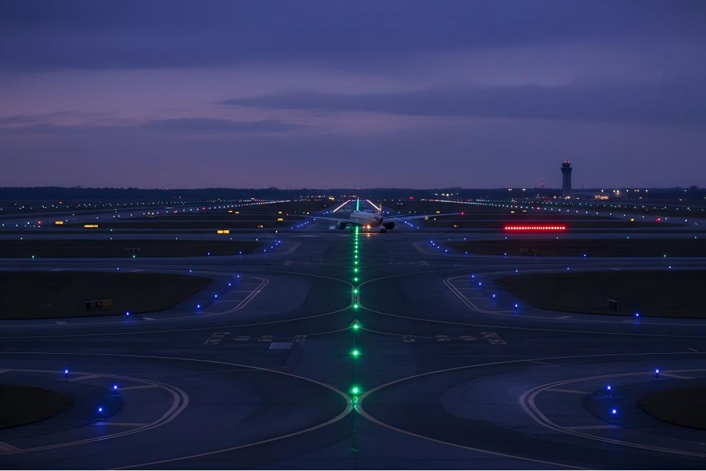
Image disclaimer: For identification and illustration only. It may show a product by another manufacturer and may not depict the exact item described; it is not a statement of any product’s quality, approval or performance. Third-party image and trademark rights belong to their owners. See full notice.
What Is It?
Taxiway lighting is the set of visual aids that guide aircraft ground movement between runways, aprons and other airport areas. Where runway lighting defines takeoff and landing, taxiway lighting defines the route and the intersections along it — helping the pilot follow the correct taxi route and, critically, helping prevent runway incursions at holding positions.
Because taxiway lighting operates continuously during ground movement in poor visibility, its colour coding and route-following behaviour need to be unambiguous — a pilot following blue edge lights and green centreline lights should never be in doubt about which taxiway they're on.
Purpose & Function
Taxiway lighting's purpose is to let an aircraft move safely and correctly around the airfield surface in the same conditions that make runway and approach lighting necessary — poor visibility, night operations — while carrying an additional responsibility that runway lighting doesn't: preventing an aircraft from entering an active runway without clearance. This is why stop bars are wired as an independently switchable circuit rather than simply left on with the rest of the taxiway lighting — their purpose is to give air traffic control a positive, remotely controllable way to block a specific holding position, making the red stop-bar light a direct, real-time reflection of current clearance status rather than a fixed marking a pilot has to remember to observe.
Where Is It Used?
Taxiway lighting systems are installed along the full taxiway network and at every intersection and holding position:
- Taxiway Edge Lights: Mark the lateral limits of the taxiway, typically blue.
- Taxiway Centreline Lights: Embedded along the taxiway centreline, typically green, guiding the aircraft's nose-wheel path.
- Stop Bars: Red inset lights across the taxiway at a runway-holding position, illuminated to indicate the position must not be crossed.
- Runway Guard Lights: Flashing yellow fixtures at holding positions, warning of the approach to an active runway.
- Clearance Bar Lights: Mark taxiway intersections to indicate an aircraft's position relative to an intersecting taxiway.
- Associated Taxiway Signs: Illuminated location, direction and mandatory signs at intersections and holding points.
Installation & Location
The taxiway lighting network is set out end to end from the surveyed centreline and edge lines of the taxiway system, with edge lights spaced at uniform intervals along both sides and centreline lights embedded at their own specified spacing down the taxiway's nose-wheel path. Stop bars, clearance bars, and runway guard lights are positioned at each holding point and intersection according to the specific geometry of that location, tied back to the same taxiway survey so every fixture's position is consistent with the overall layout rather than set independently. Each functional subsystem generally runs on its own series circuit — edge lighting, centreline lighting, and stop bars in particular are kept electrically independent so a stop bar can be switched under ATC control without affecting the taxiway edge and centreline lighting a pilot is following at the same time. Associated signage is positioned and wired alongside the lighting it complements, with cabling for the complete taxiway network routed back to the field distribution points serving that section of the airfield.
How Does It Work?
Like runway lighting, taxiway fixtures are wired into AGL series circuits fed by a CCR, with individual isolating transformers at each fixture. Stop bars are typically wired as a separate switchable circuit so they can be selectively illuminated by air traffic control at a specific holding position, independent of the general taxiway edge and centreline circuits.
Key functional aspects include:
- Colour Coding: Blue for edge, green for centreline, red for stop bars, yellow (flashing) for runway guard lights — a consistent code a pilot can rely on across airports.
- Selective Switching: Stop bars and some centreline segments near runway-holding positions can be individually controlled to reflect current clearances.
- Route Definition: Centreline lighting, in particular, is what lets an aircraft follow a taxi route accurately in low visibility without edge lights alone.
- Integration with Signage: Taxiway lighting and illuminated signage work together at intersections to remove ambiguity about location and required action.
System Architecture & Control Logic
Taxiway lighting's control hierarchy runs from the tower or ALCMS down through a bank of dedicated CCRs — one per circuit type (edge, centreline, stop bar, guard lights) — so that, for example, dimming the general taxiway circuit for a clear night doesn't affect the switchable stop bar circuit ATC needs at full intensity for an active holding position. Within each circuit, control is loop-level in the same way as runway lighting: every fixture shares one commanded current step, and a fault surfaces to the ALCMS as a voltage-rise event on that circuit rather than a signal from a specific fixture. Stop bars are the deliberate exception, wired as independently switchable circuits (and, per the stop bar monitoring unit, often with per-fixture confirmation) precisely because they gate runway access rather than simply illuminate a route. At larger or more complex airports this basic loop architecture is increasingly layered underneath an Advanced Surface Movement Guidance and Control System (A-SMGCS), where "follow-the-greens" software sequences individual centreline segments to guide a specific aircraft along a cleared route — a capability that requires the centreline circuit, or sections of it, to be segmented and individually switchable rather than a single continuously-lit loop.
Circuit & System Overview
Edge and centreline lighting form one continuously-energised circuit that simply defines the route, while stop bars and runway guard lights sit on a separately switchable circuit ATC can command independently — the two pictures combine at the cockpit into a single, unambiguous guidance and hold-point display.
Physical Construction
Across the different fixture types that make up taxiway lighting, construction follows a common pattern: a die-cast aluminium body, anodised or powder-coated against fuel spillage and de-icing fluid, houses an LED array or filtered halogen lamp behind a gasket-sealed optical prism, giving each fixture an IP67/IP68 rating regardless of its colour or role. Elevated edge fixtures mount on a frangible coupling seated in an L-867 base can so they shear away cleanly on impact, while centreline and stop bar fixtures are typically flush-mounted in an L-868 base can rated for full aircraft wheel loading, since these sit directly in the wheel path. Every fixture is fed through its own isolating transformer, sized to the fixture's wattage and housed in a nearby base can, with sealed L-823 splice connectors carrying the series circuit between fixtures and back to the primary cable. It's this consistent build — sealed housing, colour-specific optics, and a dedicated transformer per fixture — that lets edge, centreline, and stop bar lights of very different function share the same civil installation and maintenance practice.
Technical Parameters
| Parameter | Typical Value |
|---|---|
| Typical Colour — Edge | Blue |
| Typical Colour — Centreline | Green |
| Typical Colour — Stop Bar | Red |
| Typical Colour — Runway Guard Light | Yellow, flashing |
| Fixture Type | Elevated (edge) or inset/flush-mounted (centreline, stop bar) |
| Circuit Type | Series circuit fed by CCR; stop bars often on a separately switched circuit |
| Intensity Steps | Multiple selectable steps per applicable specification |
| Standards | ICAO Annex 14, FAA AC 150/5340 series, IS 7785 |
Electrical Requirements
| Requirement | Typical Value |
|---|---|
| Circuit Type | Series circuit, constant current (CCR fed); edge and centreline lighting typically on a shared circuit, with stop bars on a separately switched circuit |
| Rated Series Current | 6.6A (5-step: 2.8A / 3.4A / 4.1A / 5.2A / 6.6A), common across the taxiway lighting system |
| Isolation | Each fixture fed via its own isolating transformer (wattage varies by fixture type), off the shared series loop |
| Stop Bar Switching | Stop bar circuits wired for independent on/off control, interlocked with runway-entrance clearance logic |
| Cable Type | L-824 single-conductor, direct-burial rated, 5kV or 600V per circuit design |
| Connector | L-823 primary connector, submersible-rated splice at every fixture |
| Insulation Resistance | ≥ 50 MΩ (megger test, cable-to-ground) |
| Earthing/Grounding | Fixture bodies, base cans, and duct/cable runs bonded to the airfield earth grid |
| Fault Protection | CCR-level ground fault and open-circuit detection per circuit |
| Power Source | CCR output per circuit, regulated per ICAO/FAA intensity step schedule |
Photometric Requirements
| Parameter | Typical Value |
|---|---|
| Edge Light Intensity | 100 – 1,000 cd (blue), omnidirectional or uni-directional per fixture type |
| Centreline Light Intensity | 100 – 1,000 cd (green), typically omnidirectional |
| Stop Bar Intensity | ≥ 2,000 cd (red), uni-directional facing approaching traffic |
| Intensity Steps | 100% / 30% / 10% / 3% / 1% across the shared series circuit |
| Vertical Beam Spread | 2°–10° above horizontal (peak ~3°–4°) for edge/centreline; similar for stop bars |
| Chromaticity | Blue (edge), green (centreline), red (stop bar) within ICAO Annex 14 colour boundaries |
| Isocandela Distribution | Per ICAO Annex 14 Attachment A / FAA AC 150/5340-30 figures by fixture type |
| Test Method | Mobile photometric van/goniophotometer or fixed test bench per fixture |
Applicable Standards
ICAO Annex 14
International standards for taxiway lighting configuration, colour and switching requirements
FAA AC 150/5340-30
Design and Installation Details for Airport Visual Aids — current standard covering taxiway centreline lights, stop bars, runway guard lights, and clearance bars; consolidates and supersedes the now-cancelled AC 150/5340-28, which itself replaced AC 150/5340-19
IS 7785
Indian Standard for airfield lighting equipment and installation practice
DGCA CAR Section 4
Indian regulatory requirements for aerodrome lighting
Installation Requirements
Base Can Excavation by Fixture Type
CivilExcavate and set base cans to each fixture type's mount — inset for centreline, edge, and stop bars where flush mounting suits the surface, elevated where the location calls for it — holding each flush with the surrounding grade or pavement.
Single-Survey Set-out
CivilSet out edge lights, centreline lights, stop bars, clearance bars, runway guard lights, and associated signage from one taxiway survey, at each subsystem's own specified spacing.
Drainage Provision
CivilProvide a weep hole or drainage path at each base can to prevent water pooling around the transformer and cable entry.
Per-Subsystem Circuit Routing
ElectricalRoute edge lighting, centreline lighting, and stop bars on independent series circuits, kept electrically separate so a stop bar can be switched under ATC control without affecting the edge and centreline lighting a pilot is following.
L-823 Connector Termination
ElectricalTerminate and seal the primary connector at every fixture per manufacturer procedure, keeping each splice submersible-rated before backfill.
Isolating Transformer Matching
ElectricalConfirm each isolating transformer's wattage matches its fixture and its subsystem circuit's rated current step before connection.
Mount-Type Fixing by Fixture
MechanicalFor elevated units, torque the frangible coupling to spec; for inset units, seat the housing flush and confirm it meets wheel-load tolerance.
Pre-Energisation Sign-off
DocumentationRecord base can position, cable route, connector seal, and subsystem/circuit assignment for every fixture as-built before backfill.
Testing & Commissioning
System-Wide Insulation & Continuity Test
Pre-EnergisationMegger-test and verify loop continuity on each taxiway lighting circuit — edge, centreline, and intersection — before any circuit is energised.
CCR Brightness Step Response
EnergisationCycle each circuit through every intensity step and confirm the fixtures on that circuit respond together, ruling out marginal transformers or loose connections.
Stop Bar Interlock Test
Final AcceptanceConfirm stop bar circuits interlock correctly with runway entry lighting and the ALCMS logic — illuminated stop bars must inhibit the corresponding runway guard lights and vice versa — before hand-over.
System-Wide Photometric & Colour Verification
Final AcceptanceMeasure intensity and colour across centreline, edge, and intersection fixtures with a calibrated photometer against ICAO/FAA commissioning tolerances.
Intersection Lighting & Signage Coordination Check
Final AcceptanceConfirm intersection lighting colours and layout agree with the adjacent taxiway signage and the approved airfield layout diagram.
Documentation & As-Built Sign-off
Final AcceptanceRecord insulation, continuity, voltage, and photometric readings for each circuit alongside as-built layout in the commissioning dossier for handover.
Inspection & Maintenance
System-wide Photometric & Colour Check
AnnualTest blue edge and green centreline light output and colour across the system to catch degradation before it undermines route-following cues.
Stop Bar Circuit Test
MonthlyTest stop bar switching and control circuits given the direct runway-incursion safety implication of a fault here.
Centreline Fixture Wear Inspection
Semi-annualInspect inset centreline fixtures for accelerated lens and housing wear from continuous wheel loading.
Intersection Lighting & Signage Audit
Semi-annualReview lighting and signage consistency at complex taxiway intersections, a recurring factor in ground-movement incidents.
Lens Cleaning Programme
QuarterlyMaintain a system-wide cleaning schedule so contamination doesn't shift edge or centreline colours toward an ambiguous hue.
Common Field Issues
Colour Confusion from Fixture Degradation
A failing or dirty lens can shift blue edge or green centreline lighting toward an ambiguous colour, undermining the route-following cues pilots rely on.
Stop Bar Switching Faults
Because stop bars are often on a separately controlled circuit, wiring or control-system faults here have a direct runway-incursion safety implication and are treated with particular urgency.
Centreline Fixture Wear from Wheel Loading
Inset centreline fixtures sit directly in the aircraft's wheel path and see continuous mechanical loading, accelerating lens and housing wear compared to edge fixtures.
Intersection Confusion
Poorly maintained or inconsistent lighting and signage at complex taxiway intersections is a recurring contributing factor in ground-movement incidents.
Troubleshooting Guide
Blue or Green Fixture Reading as an Ambiguous Colour
Stop Bar Circuit Fault
Accelerated Wear on Inset Centreline Fixtures
Recurring Confusion at a Complex Intersection
Failure Modes & Root Causes
Colour-Cue Degradation from Lens Fault
Stop Bar Circuit Fault
Inset Centreline Fixture Wear
Intersection Lighting Inconsistency
Safety & Operational Notes
Series Circuit Isolation
Electrical SafetyDe-energise and lock out the CCR for the affected loop and verify zero energy before opening any base can, remembering that a single taxiway circuit can feed a long run of edge and centreline fixtures.
Colour/Circuit Verification
ComplianceConfirm blue edge, green centreline, and yellow caution elements are reconnected to their correct circuits before re-energising; a swapped colour undermines the unambiguous route-following the system is designed to provide.
Airside Work Coordination
OperationalTaxiway lighting is relied on for ground movement in poor visibility; coordinate with ATC/ground control and raise a NOTAM for any section that will be dark, keeping personnel and vehicles clear of active taxi routes.
FOD Control Across the Worksite
OperationalKeep tools, fasteners, and gaskets accounted for at every base can opened along the worksite, and secure or remove loose material before reinstating fixtures.
Insulation Test Before Re-Energisation
Electrical SafetyMegger test each affected circuit after any cable, connector, or transformer work, since a residual fault at re-energisation can trip the CCR or take down an entire taxiway segment.
PPE & Grounding
Personnel SafetyUse insulated tools and appropriate PPE when working on series-circuit connections, and confirm bonding/grounding of each base can before reconnecting.
Restore to Compliant State
ComplianceWalk the affected section to confirm colour, intensity, and route continuity before closing out the work and cancelling the NOTAM.
Engineering & Expert Notes
A Single Circuit Can Span a Long, Visually Diverse Route
DesignBecause one taxiway circuit can feed edge and centreline fixtures across very different pavement ages and drainage conditions, a fault-finding walk should cover the whole run rather than assuming a problem is localised near where a report came in.
Colour Consistency Along the Route, Not Just Fixture-by-Fixture
ComplianceLamp or LED colour temperature can drift subtly across a long taxiway route even when every individual fixture passes chromaticity spec on its own; check colour consistency by walking a full section rather than testing fixtures in isolation.
Trend Loop Readings, Don't Just Spot-Check
TroubleshootingMoisture ingress at an L-823 connector usually shows up first as a slow drift in loop insulation resistance, not a hard fault. Logging megger readings over successive maintenance cycles catches a failing splice months before it takes the loop down.
Size the Transformer to the Load, Not the Legacy Lamp
ElectricalReusing an isolating transformer sized for the old incandescent wattage on a much lower-draw LED fixture is a common source of premature transformer failure and nuisance loop trips; re-select VA rating against the actual LED load rather than assuming the existing transformer is "close enough."
Balance Loops Sharing One CCR
DesignWhere multiple series loops run off a single CCR, unequal loop lengths or lamp counts between loops can produce visibly uneven brightness along a taxiway even though each individual fixture tests within photometric tolerance. Balance loop impedance at the design stage, not after commissioning complaints.
De-Icing Fluid Ages Seals Faster Than UV Alone
DurabilityRepeated exposure to glycol-based de-icing fluid degrades gaskets and lens seals faster than sun and weather alone, especially on sections that see heavy de-icing traffic. Specify seal materials rated for glycol contact and inspect gasket condition at overhaul, not only at initial install.
Frequently Asked Questions
Short answers about taxiway lighting: colours, components, switching, standards and maintenance.
Q1What is taxiway lighting?
Taxiway lighting is the set of visual aids that guide aircraft between runways, aprons and other airport areas. Where runway lighting defines take-off and landing, taxiway lighting defines the route and its intersections.
Q2What colours are used in taxiway lighting?
Blue for taxiway edge lights, green for centreline lights, red for stop bars and flashing yellow for runway guard lights. The code is consistent across airports so pilots can rely on it.
Q3What components make up a taxiway lighting system?
Edge lights, centreline lights, stop bars, runway guard lights, clearance bar lights and associated illuminated signs at intersections and holding points.
Q4Why are stop bars on a separate circuit?
Stop bars are typically on a separately switched circuit so they can be selectively controlled to reflect current clearances. A fault here has a direct runway-incursion safety implication.
Q5Are taxiway edge and centreline lights elevated or inset?
Edge lights are typically elevated, while centreline and stop bar lights are inset (flush-mounted) in the pavement. Centreline fixtures see continuous wheel loading and wear faster.
Q6Which standards apply to taxiway lighting?
The main references are ICAO Annex 14, FAA AC 150/5340-30 (design and installation details for airport visual aids), IS 7785 and DGCA CAR Section 4 for India. Always verify the current edition.
Q7How often should taxiway lighting be maintained?
Typical intervals are monthly stop bar circuit tests, semi-annual centreline wear and intersection lighting and signage audits, and an annual system-wide photometric and colour check. Your airport's approved maintenance programme takes precedence.
Q8Why does a blue or green taxiway light look the wrong colour?
A degrading or dirty lens, or a faded filter, can shift the perceived colour. Take a photometric colour reading against the chromaticity spec, then clean the lens or replace the filter or LED module.
Related Components
Go Beyond the Component. Understand the Complete AGL System.
You have explored the component. Now understand how it works within the complete Airfield Ground Lighting system.
Learn AGL from fundamentals to design, installation, testing, photometry, commissioning, maintenance and troubleshooting through structured technical training at Precision AGL Academy.
Build practical knowledge. Understand the circuit. Read the standards. Troubleshoot with confidence.
Your next step in AGL starts here.
Need help with taxiway lighting layout, stop bar switching, or compliance review?
Precision AGL Academy advises on taxiway lighting design, intersection layout, and standards compliance across ICAO, FAA and Indian requirements.
Follow the Academy
Important Notice, Disclaimer & Limitation of Liability
Please read before relying on any content on this page.
- Purpose and intended users. This page on Taxiway Lighting is an independent educational and informational reference for competent, suitably trained and authorised airfield ground lighting (AGL) and aerodrome electrical personnel. It is not professional engineering, legal or regulatory advice, and using it does not create any professional or client relationship.
- Safety. Work on series circuits, constant current regulators (CCRs), isolating transformers, cables, connectors and lighting equipment can be fatal. Always apply the aerodrome’s permit-to-work and isolation/LOTO procedures, prove dead, use correctly rated instruments and PPE, and follow the manufacturer’s instructions. Nothing here authorises work on live equipment or the bypassing of any safety device or interlock.
- Aviation operations. Nothing here authorises installation, modification, energisation, adjustment, return to service, a change of operating category (CAT I/II/III), a NOTAM or any aerodrome certification or approval decision. These rest with the aerodrome operator, the air navigation service provider and the competent regulator.
- Specifications, ratings and typical values. Descriptions, parameters, ratings, dimensions, photometric values, wattages, service lives, maintenance tasks and intervals, failure modes, certifications (for example CE, FCC, UL or IEC marks) and part or type designations are general, typical and indicative. They may not match any particular product, make, model or version, and they are not a datasheet, design, specification, selection, sizing, procurement or acceptance criterion. The manufacturer’s current documents, the approved design and the project specification prevail.
- Standards and regulations. References to ICAO, FAA, IEC, IEEE, ISO, BIS, DGCA and other standards are paraphrased summaries for orientation only. They may be incomplete or out of date, and standards are revised from time to time. Consult the current official editions. Following this content does not guarantee compliance with any law, standard or regulatory approval, and the regulator’s requirements always prevail.
- No warranty. Content is provided “as is” and “as available”, without warranty of any kind, express or implied, including accuracy, completeness, currency or fitness for a particular purpose. Real installations differ in design, equipment make and model, age and condition.
- Limitation of liability. To the fullest extent permitted by applicable law, Precision AGL Academy, Precision AGL Solutions and their owners, authors and contributors are not liable for any injury, death, loss, damage, downtime, penalty or regulatory consequence, whether direct or indirect, arising from the use of, reliance on, or inability to use this content. Nothing in this notice excludes or limits any liability that cannot lawfully be excluded or limited.
- Independence, brands and no endorsement. This is an independent publication. It is not affiliated with, sponsored by or endorsed by ICAO, the FAA, the IEC, DGCA, AAI, any airport, regulator, supplier or equipment manufacturer. Third-party names, product designations, standard designations and trademarks (including Megger®, Siemens, Eaton, Crouse-Hinds, ADB SAFEGATE, Fluke, ABB and Honeywell) belong to their respective owners and are used only for identification and description. Mention of a brand, product or supplier is not a recommendation, and we do not sell, supply or quote for any component described.
- Images and third-party content. Images and illustrations are shown to help identify the type of component. They may show products of various manufacturers, may not depict the exact item described, and are not a statement about any product’s quality, approval or performance. Copyright and trademarks in third-party images, logos and photographs belong to their respective owners and are not claimed as ours. If you are a rights holder and want an image removed, replaced or credited, email precisionaglsolutions@gmail.com with the page address and we will act promptly.
- Training and services. Mentions of training, courses, consultation, advice, selection, installation, calibration or other support, including the “Learn…Certify” pathway, describe learning stages and are not an offer, quotation, tender or promise of any result. Contacting us or our replying creates no engagement or duty of care; an engagement exists only under a written agreement. We are not a regulator or certification body, and completing any course or reading this content is not a certification, accreditation or authorisation to work on any aerodrome.
- Copyright, privacy and corrections. © 2026 Precision AGL Academy. All rights reserved. Text, structure, compilations and diagrams may be viewed for personal reference and internal training only; any other copying, republication or commercial use needs our written permission. If you email, telephone or message us, we use your details only to respond and handle your matter, in line with applicable Indian law including the Digital Personal Data Protection Act, 2023; please do not send confidential or security-sensitive information. To display this page your browser requests fonts, icons and images from third-party servers, which receive your IP address and browser details under their own policies. Content is reviewed periodically with no obligation to update. To report an error, safety concern or rights issue, write to precisionaglsolutions@gmail.com.