Surface Movement Radar
A high‑performance surveillance system that provides real‑time detection and tracking of aircraft and vehicles on the airfield surface. Surface Movement Radar (SMR) enhances situational awareness for Air Traffic Control, enabling safe and efficient ground movement management even in low visibility conditions.
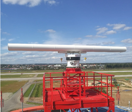
Image disclaimer: For identification and illustration only. It may show a product by another manufacturer and may not depict the exact item described; it is not a statement of any product’s quality, approval or performance. Third-party image and trademark rights belong to their owners. See full notice.
What Is It?
A Surface Movement Radar (SMR) is a specialized radar system designed to detect and track the position, speed, and heading of aircraft and vehicles operating on the airport surface—including runways, taxiways, and aprons. Operating in the X‑band (8‑12 GHz) or Ku‑band (12‑18 GHz), SMR provides high‑resolution detection with range resolution as fine as 5‑15 metres, enabling controllers to distinguish between multiple targets in close proximity. The radar antenna is typically mounted on a tower adjacent to the control tower or on a dedicated mast, providing a 360° scan of the airfield surface. The system processes radar returns to generate a real‑time display overlay on airport maps, often integrated with ADS‑B, multilateration, and other surveillance sources to provide a comprehensive surface picture. SMR is a critical component of Advanced Surface Movement Guidance and Control Systems (A‑SMGCS), enhancing safety and throughput, particularly during low visibility operations (RVR < 400m) where visual observation is limited.
Purpose & Function
Surface movement radar exists specifically for the situation where a controller's own eyes are the least reliable source of surface traffic information: low visibility conditions where fog, rain, or darkness make it impossible to visually confirm an aircraft or vehicle's position from the tower. Because SMR's X-band or Ku-band returns are essentially unaffected by the same weather that degrades human vision, the radar's purpose is to maintain the same level of surface awareness in RVR below 400 metres that a controller would otherwise only have in clear daylight. Fusing that radar picture with ADS-B and multilateration data extends this further, giving controllers identity information alongside position so a return on the radar display can be matched to a specific aircraft or vehicle rather than remaining an anonymous target.
Where Is It Used?
Surface Movement Radar is deployed at airports of all sizes where enhanced ground surveillance is required:
- Air Traffic Control Towers: Providing controllers with a high‑fidelity, real‑time display of all surface traffic for safe and efficient ground movement management.
- ATC Approach Control Rooms: Integrating SMR data into the broader surveillance picture alongside approach radar and ADS‑B.
- Airport Operations Centers: Monitoring surface activity for overall airport situational awareness and resource management.
- A‑SMGCS Systems: Serving as the primary surveillance sensor for Advanced Surface Movement Guidance and Control Systems, enabling automated conflict detection and alerting.
- Runway Incursion Prevention Systems: Providing target detection to Runway Status Light (RWSL) systems and other safety alerting systems.
- Low Visibility Operations: Enabling safe ground movements when RVR is below 400m (CAT II/III conditions) where visual observation is insufficient.
- Apron Management: Monitoring aircraft and vehicle movements on the apron for improved ground handling coordination.
- Large Hub Airports: Managing complex surface traffic with multiple simultaneous movements, reducing delays and enhancing safety.
Installation & Location
The SMR antenna is mounted at height on the control tower roof or a dedicated tower structure, sited for line-of-sight coverage across the full manoeuvring area with minimal shadowing from buildings, terrain, or other masts. Foundation and mast design account for the antenna's rotating mass and wind loading, with the mast earthed and lightning-protected given its elevated, exposed position. Signal and data cabling runs from the antenna head down the mast to the processing unit in the tower equipment room, typically over fibre to keep the run immune to the electromagnetic environment around the radar itself; siting is also checked against other radars and radio installations on the airfield to avoid mutual interference.
How Does It Work?
The Surface Movement Radar operates on pulse‑based radar principles, transmitting short, high‑frequency pulses and receiving the echoes from reflecting targets. Key functional aspects include:
- Antenna Scan: The rotating parabolic or slotted‑array antenna provides a continuous 360° azimuth scan, typically at 20‑60 revolutions per minute, covering the entire airfield surface.
- Pulse Transmission: The radar transmits short pulses (typically 0.5‑2 µs) at high peak power (5‑100 kW) in the X‑band or Ku‑band, with a pulse repetition frequency (PRF) of 1‑10 kHz.
- Echo Reception: The radar receives the reflected echoes (from aircraft, vehicles, buildings, and other surfaces) and processes the signals to extract range, azimuth, and radial velocity information.
- Moving Target Indication (MTI): SMR uses Doppler processing (MTI or Pulse‑Doppler) to discriminate moving targets from stationary clutter (buildings, terrain, static aircraft), isolating only the moving targets of interest.
- Target Extraction & Tracking: The radar signal processor extracts target centroids (position and velocity) and passes them to the tracker, which uses Kalman filtering or similar algorithms to maintain continuous target tracks, smoothing position updates and predicting future positions.
- Clutter Suppression: Advanced filtering techniques (CFAR, map‑based clutter mapping) suppress false returns from terrain, buildings, and parked aircraft, ensuring only relevant targets are displayed.
- Display Integration: The processed track data is transmitted to the ATC display system, where targets are overlaid on an airport map with labels, track history, and velocity vectors for clear operator interpretation.
Modern SMR systems are often integrated with multilateration and ADS‑B to provide a fused surveillance picture, improving accuracy and coverage in areas where radar returns may be shadowed.
System Architecture & Control Logic
The Surface Movement Radar feeds raw target detections into the A-SMGCS or ALCMS processing chain rather than making any lighting decision at the sensor head itself. The antenna and receiver produce return echoes, which a radar processor converts into tracked targets (position, heading, identity where fused with other sensors); that track data is what actually reaches the A-SMGCS or ALCMS server, typically over the airfield's fibre/Ethernet backbone rather than a dedicated link. Where the airfield uses Runway Status Lights, the A-SMGCS logic combines SMR tracks with other surveillance sources to decide when an aircraft or vehicle occupies or is approaching a runway, and that decision — not the raw radar return — is what triggers the corresponding CCR and stop bar or runway status light circuit. A radar fault therefore shows up as a gap in surveillance coverage at the A-SMGCS level, not as a lighting fault.
SMR Antenna & Receiver
Transmits pulses, captures raw echo returns
Radar Processor
Converts returns into tracked targets (position, heading)
A-SMGCS / ALCMS Server
Fuses tracks with other surveillance, decides runway occupancy
CCR → Runway Status / Stop Bar Lights
Actuated only on the fused decision, not the raw radar return
Scan‑to‑Track Pipeline
Physical Construction
The radar antenna — a parabolic dish or planar slotted-array panel — is mounted on a motor-driven rotating pedestal atop a dedicated tower or mast adjacent to the control tower, engineered to maintain the specified rotation speed and pointing accuracy through wind loading up to the site's design limits. A radome typically encloses the antenna to protect it from precipitation, ice, and debris while remaining transparent to the X-band or Ku-band signal, and the pedestal drive motor and slip rings are housed in a weatherproof base unit rated to at least IP65/NEMA 4X. Transmitter, receiver, and signal-processing electronics are housed either in the tower base or in a nearby equipment room, connected to the antenna via low-loss waveguide or coaxial feed running up the tower structure. Outdoor units, cabling entries, and the antenna drive assembly are all built for continuous unattended exposure to airfield weather, with lightning protection and surge suppression fitted at the base of the tower to protect the sensitive receiver electronics from strikes to the elevated structure.
Technical Parameters
| Parameter | Typical Value |
|---|---|
| Frequency Band | X‑band (8‑12 GHz) or Ku‑band (12‑18 GHz) |
| Peak Transmit Power | 5‑100 kW (depending on range requirement) |
| Pulse Width | 0.5‑2 µs (narrow pulse for high range resolution) |
| Pulse Repetition Frequency (PRF) | 1‑10 kHz (typically 3‑6 kHz) |
| Range Coverage | 5‑20 km (typical airfield coverage) |
| Range Resolution | 5‑15 metres (depending on pulse width) |
| Azimuth Coverage | 360° (continuous rotation) |
| Azimuth Resolution | 0.5°‑2° (depending on antenna beamwidth) |
| Antenna Type | Parabolic dish or slotted‑array (planar) |
| Antenna Rotation Speed | 20‑60 RPM (configurable) |
| Antenna Beamwidth | 0.5°‑2° (horizontal), 15°‑30° (vertical) |
| MTI/Doppler Processing | Yes (Pulse‑Doppler or MTI with clutter suppression) |
| Target Tracking Capacity | 500+ simultaneous targets |
| Data Output | ASTERIX, Ethernet (TCP/IP), serial (RS‑422), CCTV overlay |
| Power Supply | 120/230 VAC (single‑phase) or 400 VAC (three‑phase) |
| Power Consumption | 2‑15 kW (depending on range and technology) |
| Operating Temperature | -25°C to +55°C (outdoor electronics) |
| Protection Class | IP65 / NEMA 4X (antenna and outdoor units) |
| Certifications | ICAO Doc 9830, EUROCAE ED-116, FAA JO 6330.36, CE |
Electrical Requirements
| Requirement | Typical Value |
|---|---|
| Supply Type | 120/230 VAC single-phase or 400 VAC three-phase, backed by UPS and standby generator |
| Power Consumption | 2–15 kW (depending on range and technology) |
| Circuit Protection | Dedicated circuit breaker/isolator at the tower or equipment room distribution board |
| Cabling | Dedicated feeder from the distribution point to the antenna pedestal/processing cabinet, sized to rated load |
| Rotary Joint / Slip Ring | Power and signal transfer across the rotating antenna via slip ring or rotary joint |
| Surge Protection | SPDs fitted at the power and data cable entries to the processing cabinet |
| Insulation Resistance | ≥ 50 MΩ (megger test, cable-to-ground, at commissioning) |
| Earthing/Grounding | Antenna pedestal, tower structure, and processing cabinet bonded to the airfield earth grid |
| Fault Protection | Continuous system monitoring with alarm reporting to ATC/maintenance on power or subsystem fault |
Applicable Standards
ICAO Doc 9830
Advanced Surface Movement Guidance and Control Systems (A‑SMGCS) Manual — operational requirements including SMR as a surveillance sensor
EUROCAE ED‑116
MOPS for Surface Movement Radar sensor systems used in A‑SMGCS
FAA Order JO 6330.36
Maintenance of Airport Surface Detection Equipment, Model X (ASDE‑X) facilities
EUROCAE ED‑87
Minimum Aviation System Performance Specification (MASPS) for A‑SMGCS Levels 1 and 2
Installation Requirements
Tower/Mast Foundation & Line-of-Sight Check
CivilConfirm the tower or mast foundation is engineered for the antenna's rotating mass and wind loading, and verify line-of-sight coverage across the full manoeuvring area with minimal shadowing before erection.
Antenna & Radome Installation
MechanicalMount the antenna and radome on the rotating pedestal, confirming the pedestal drive motor and slip rings are sealed to their rated protection class before commissioning.
Mast Earthing & Lightning Protection
ElectricalBond the mast to a dedicated earthing and lightning-protection system, fitting surge suppression at the base of the tower given the elevated, exposed position of the receiver electronics.
Fibre Signal Run
ElectricalRun signal and data cabling from the antenna head down the mast to the processing unit over fibre, keeping the run immune to the electromagnetic environment around the radar itself.
Interference Coordination Check
DocumentationCheck the proposed siting against other radars and radio installations on the airfield to avoid mutual interference before the radar is brought into service.
Pre-Commissioning Sign-off
DocumentationRecord antenna position, earthing, and cable routing as-built before commissioning testing begins.
Testing & Commissioning
Antenna Rotation & Pointing Check
Pre-EnergisationVerify the pedestal drive maintains the specified rotation speed and pointing accuracy through the site's design wind loading before radiating.
Transmitter Power & Pulse Verification
EnergisationConfirm peak transmit power, pulse width, and PRF are within spec for the licensed X/Ku-band operation.
MTI / Clutter Suppression Test
Final AcceptanceConfirm Doppler/MTI processing correctly discriminates moving targets from stationary clutter such as buildings and parked aircraft.
Target Tracking Accuracy Test
Final AcceptanceRun known test targets across the coverage area and verify range, azimuth, and track continuity meet resolution specifications.
A-SMGCS / ALCMS Interface Test
Final AcceptanceConfirm processed track data reaches the A-SMGCS or ALCMS server correctly over the airfield fibre/Ethernet backbone.
Sensor Fusion Cross-Check
Final AcceptanceWhere integrated with multilateration or ADS-B, confirm fused tracks agree across sources, particularly in radar-shadowed areas.
Documentation & As-Built Sign-off
Final AcceptanceRecord transmitter test results, tracking accuracy figures, and interface verification in the commissioning dossier for handover.
Inspection & Maintenance
Clutter Map Review
AnnualReview and update the clutter map to account for new structures or stationary objects on the airfield.
Transmitter / Receiver Performance Check
AnnualTest transmitter output and receiver sensitivity against baseline to catch gradual performance degradation.
Antenna & Radome Inspection
Semi-annualCheck the antenna and radome for physical damage or contamination that could cause shadowing or attenuation.
Data Latency Check
Semi-annualMeasure processing and display latency to confirm it remains within operational requirements.
RF Interference Survey
AnnualSurvey the local RF environment for new sources of interference from other radio systems.
Common Field Issues
Clutter from Stationary Objects
Buildings, hangars, parked aircraft, and terrain can produce strong clutter returns that mask moving targets. Advanced clutter mapping and MTI processing are required, but regular calibration and tuning are necessary to optimise performance as the airfield environment changes (new buildings, parked aircraft positions).
Rain Clutter & Attenuation
Heavy rain can attenuate radar signals and produce clutter returns, particularly in X‑band systems. Real‑time rain clutter suppression algorithms and, in some systems, dual‑polarisation or frequency agility are used to mitigate this.
Shadowing & Multipath
Tall structures (control towers, hangars) can create radar shadows, while multipath reflections from large buildings can cause ghost targets. Careful antenna siting and site‑specific calibration are essential.
Transmitter/Receiver Performance Degradation
Magnetron or solid‑state amplifiers degrade over time, reducing transmit power and receiver sensitivity. Regular maintenance and performance testing (using a test target or radar cross‑section calibration) are required to ensure coverage remains within specifications.
Data Latency
Processing delays in the radar signal processor or track extraction can introduce latency in the displayed target position, which is critical for real‑time control. Ensure processors meet performance specifications and monitor system timing.
Interference from Other Radio Systems
Other radar systems, communication transmitters, or satellite uplinks can interfere with SMR operation. Frequency coordination and the use of interference‑resistant techniques (e.g., frequency diversity) are recommended.
Troubleshooting Guide
Moving Targets Masked Near Buildings or Parked Aircraft
Reduced Coverage or False Returns in Heavy Rain
Ghost Targets or Blind Spots Near Tall Structures
Reduced Detection Range Over Time
Delayed or Jumping Target Position on Display
Failure Modes & Root Causes
Antenna / Radome Degradation
Transmitter / Receiver Performance Degradation
Clutter Map Drift from Stationary Objects
Rain Clutter and Signal Attenuation
RF Interference from Other Radio Systems
Data Latency / Processing Fault
Shadowing and Multipath Near Tall Structures
Safety & Operational Notes
RF / Microwave Exposure
Personnel SafetyThe transmitter can produce high peak power (5-100 kW) in the X-band or Ku-band; do not work in front of the antenna aperture while the radar is transmitting, and follow the manufacturer's RF safety exclusion distance and lockout procedure for maintenance access.
Rotating Antenna Hazard
MechanicalThe parabolic or slotted-array antenna rotates continuously at 20-60 RPM during operation; lock out antenna rotation before working on or near the mast head, and never assume a momentarily stopped antenna will stay stopped.
Working at Height
Personnel SafetyAntenna and mast-head access is typically on the control tower roof or a dedicated tower structure; use fall-arrest equipment and a stable access platform, and avoid work during high wind given the mast's elevated, exposed position.
Lightning Exposure
Electrical SafetyAs one of the tallest structures in its immediate area, the mast is a lightning attraction point; avoid working at or near the antenna during an electrical storm, and confirm mast earthing and lightning protection are intact after any strike.
High-Power Electrical Isolation
Electrical SafetyDe-energise and lock out the radar's mains supply (and, where fitted, generator/UPS backup) before internal work on the transmitter or power supply, and verify zero energy given the multi-kW power levels involved.
Airside/ATC Coordination
OperationalSMR is a primary surface-surveillance tool for controllers; coordinate any outage with ATC and raise a NOTAM, since taking it down removes a safety-critical situational-awareness capability for ground movement.
Restore to Compliant State
ComplianceConfirm the radar returns full 360° coverage with correct range resolution before closing out the work and returning it to operational service.
Engineering & Expert Notes
New Construction Can Create a Coverage Shadow
SitingA new hangar, terminal extension, or even a temporary crane erected within line of sight of the antenna can create a permanent blind spot in ground coverage without any fault on the radar itself; treat any new tall structure near the airfield as a trigger to re-verify coverage, not just changes made to the radar installation.
Weather Clutter Degrades Gradually With Radome Condition
MaintenanceA degraded or contaminated radome (dirt film, ice buildup, coating wear) increases signal attenuation and can be mistaken for a transmitter power issue during heavy rain or snow; check radome condition and cleanliness before troubleshooting a weather-correlated performance complaint as an electronics fault.
Track Magnetron or Transmitter Output Over Time
ReliabilityTransmitter output power on older magnetron-based systems declines gradually over years of service rather than failing suddenly; logging output power at each scheduled maintenance visit reveals a slow decline trend long before it becomes an operationally noticeable range-reduction complaint.
Rotary Joint Wear Shows Up as Intermittent Signal Dropout
MechanicalThe rotary joint connecting the stationary waveguide to the continuously rotating antenna is a common source of intermittent signal degradation that correlates with antenna position rather than weather or transmitter condition; a fault that seems to come and go with the sweep is worth checking here before assuming it's a transmitter issue.
Lightning Protection Needs Post-Strike Verification, Not Just Visual Check
ElectricalA lightning strike near the mast can degrade the earthing system's actual resistance without leaving any visible sign at the structure; after a known nearby strike, verify earth resistance with a proper test rather than relying on a visual inspection of the bonding connections alone.
Antenna Rotation Speed Drift Is Easy to Miss
VerificationA motor or drive system that's slowly slowing down from its rated RPM can still produce a usable-looking picture at reduced update rate, which delays operator complaints; verify actual rotation speed against spec at scheduled maintenance rather than relying on the display appearing normal.
Frequently Asked Questions
Short answers about surface movement radar: surface surveillance, specifications, power, standards and maintenance.
Q1What is a surface movement radar?
A Surface Movement Radar (SMR) is a specialised radar that detects and tracks the position, speed and heading of aircraft and vehicles on runways, taxiways and aprons, operating in the X-band (8-12 GHz) or Ku-band.
Q2Why is surface movement radar needed?
It covers situations where a controller's own eyes are least reliable, such as fog, rain or darkness, by giving a real-time picture of surface traffic.
Q3Where is surface movement radar deployed?
At airports of all sizes needing enhanced ground surveillance, with the display used by controllers in air traffic control towers.
Q4How does it work?
It transmits short high-frequency pulses from a rotating antenna and receives echoes from targets, using MTI or Doppler processing with clutter suppression to separate moving targets from fixed objects.
Q5What are the typical specifications?
Range coverage of 5-20 km, range resolution 5-15 m, azimuth resolution 0.5-2 degrees, antenna rotation 20-60 RPM, tracking of 500 or more targets, and outputs such as ASTERIX, Ethernet, RS-422 and CCTV overlay.
Q6What electrical supply does it need?
120/230 VAC single-phase or 400 VAC three-phase, typically 2-15 kW, backed by UPS and a standby generator, with a slip ring or rotary joint across the rotating antenna and SPDs at power and data entries.
Q7Which standards apply?
ICAO Doc 9830 (A-SMGCS Manual), EUROCAE ED-116 (MOPS for SMR sensor systems), EUROCAE ED-87 (MASPS for A-SMGCS Levels 1 and 2) and FAA Order JO 6330.36 (maintenance of ASDE-X facilities).
Q8How often should surface movement radar be maintained?
Semi-annually for antenna and radome inspection and data latency checks, and annually for clutter map review, transmitter and receiver performance checks and an RF interference survey.
Q9Why are moving targets masked near buildings or parked aircraft?
Strong clutter returns from stationary structures may not be suppressed enough. Review the clutter map against the current airfield layout and check the MTI processing settings.
Related Components
Go Beyond the Component. Understand the Complete AGL System.
You have explored the component. Now understand how it works within the complete Airfield Ground Lighting system.
Learn AGL from fundamentals to design, installation, testing, photometry, commissioning, maintenance and troubleshooting through structured technical training at Precision AGL Academy.
Build practical knowledge. Understand the circuit. Read the standards. Troubleshoot with confidence.
Your next step in AGL starts here.
Need expert guidance on Surface Movement Radar selection, siting, or integration for your airport?
Precision AGL Academy provides advice on radar types, site surveys, clutter mitigation, and integration with A‑SMGCS and RWSL systems.
Follow the Academy
Important Notice, Disclaimer & Limitation of Liability
Please read before relying on any content on this page.
- Purpose and intended users. This page on Surface Movement Radar is an independent educational and informational reference for competent, suitably trained and authorised airfield ground lighting (AGL) and aerodrome electrical personnel. It is not professional engineering, legal or regulatory advice, and using it does not create any professional or client relationship.
- Safety. Work on series circuits, constant current regulators (CCRs), isolating transformers, cables, connectors and lighting equipment can be fatal. Always apply the aerodrome’s permit-to-work and isolation/LOTO procedures, prove dead, use correctly rated instruments and PPE, and follow the manufacturer’s instructions. Nothing here authorises work on live equipment or the bypassing of any safety device or interlock.
- Aviation operations. Nothing here authorises installation, modification, energisation, adjustment, return to service, a change of operating category (CAT I/II/III), a NOTAM or any aerodrome certification or approval decision. These rest with the aerodrome operator, the air navigation service provider and the competent regulator.
- Specifications, ratings and typical values. Descriptions, parameters, ratings, dimensions, photometric values, wattages, service lives, maintenance tasks and intervals, failure modes, certifications (for example CE, FCC, UL or IEC marks) and part or type designations are general, typical and indicative. They may not match any particular product, make, model or version, and they are not a datasheet, design, specification, selection, sizing, procurement or acceptance criterion. The manufacturer’s current documents, the approved design and the project specification prevail.
- Standards and regulations. References to ICAO, FAA, IEC, IEEE, ISO, BIS, DGCA and other standards are paraphrased summaries for orientation only. They may be incomplete or out of date, and standards are revised from time to time. Consult the current official editions. Following this content does not guarantee compliance with any law, standard or regulatory approval, and the regulator’s requirements always prevail.
- No warranty. Content is provided “as is” and “as available”, without warranty of any kind, express or implied, including accuracy, completeness, currency or fitness for a particular purpose. Real installations differ in design, equipment make and model, age and condition.
- Limitation of liability. To the fullest extent permitted by applicable law, Precision AGL Academy, Precision AGL Solutions and their owners, authors and contributors are not liable for any injury, death, loss, damage, downtime, penalty or regulatory consequence, whether direct or indirect, arising from the use of, reliance on, or inability to use this content. Nothing in this notice excludes or limits any liability that cannot lawfully be excluded or limited.
- Independence, brands and no endorsement. This is an independent publication. It is not affiliated with, sponsored by or endorsed by ICAO, the FAA, the IEC, DGCA, AAI, any airport, regulator, supplier or equipment manufacturer. Third-party names, product designations, standard designations and trademarks (including Megger®, Siemens, Eaton, Crouse-Hinds, ADB SAFEGATE, Fluke, ABB and Honeywell) belong to their respective owners and are used only for identification and description. Mention of a brand, product or supplier is not a recommendation, and we do not sell, supply or quote for any component described.
- Images and third-party content. Images and illustrations are shown to help identify the type of component. They may show products of various manufacturers, may not depict the exact item described, and are not a statement about any product’s quality, approval or performance. Copyright and trademarks in third-party images, logos and photographs belong to their respective owners and are not claimed as ours. If you are a rights holder and want an image removed, replaced or credited, email precisionaglsolutions@gmail.com with the page address and we will act promptly.
- Training and services. Mentions of training, courses, consultation, advice, selection, installation, calibration or other support, including the “Learn…Certify” pathway, describe learning stages and are not an offer, quotation, tender or promise of any result. Contacting us or our replying creates no engagement or duty of care; an engagement exists only under a written agreement. We are not a regulator or certification body, and completing any course or reading this content is not a certification, accreditation or authorisation to work on any aerodrome.
- Copyright, privacy and corrections. © 2026 Precision AGL Academy. All rights reserved. Text, structure, compilations and diagrams may be viewed for personal reference and internal training only; any other copying, republication or commercial use needs our written permission. If you email, telephone or message us, we use your details only to respond and handle your matter, in line with applicable Indian law including the Digital Personal Data Protection Act, 2023; please do not send confidential or security-sensitive information. To display this page your browser requests fonts, icons and images from third-party servers, which receive your IP address and browser details under their own policies. Content is reviewed periodically with no obligation to update. To report an error, safety concern or rights issue, write to precisionaglsolutions@gmail.com.