Series Circuit Earth‑Fault Detector
A critical protection device that continuously monitors the AGL series circuit for insulation degradation and earth‑fault conditions. Detects current leakage to earth, providing early warning of cable damage, moisture ingress, or fixture faults before they escalate into hazardous failures.
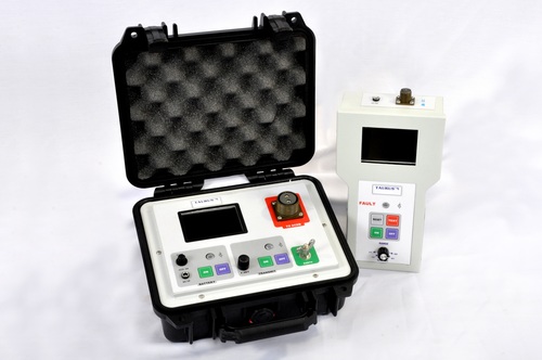
Image disclaimer: For identification and illustration only. It may show a product by another manufacturer and may not depict the exact item described; it is not a statement of any product’s quality, approval or performance. Third-party image and trademark rights belong to their owners. See full notice.
What Is It?
A Series Circuit Earth‑Fault Detector (also known as a ground‑fault detector or leakage monitor) is a specialised protection device that monitors the insulation integrity of an AGL series lighting circuit. It continuously measures the current flowing from the circuit conductors to earth (ground) and provides an alarm or trips the system when a fault current exceeds a preset threshold.
In AGL series circuits, the isolating transformers are designed with primary and secondary windings that are electrically isolated from each other and from earth. However, cable insulation can degrade over time due to ageing, mechanical damage, moisture ingress, or chemical attack. When insulation fails, a leakage path to earth is created, which can cause nuisance tripping, create a shock hazard, or lead to a complete circuit failure. The earth‑fault detector provides an early warning of such degradation, allowing maintenance to be scheduled before a full failure occurs.
Purpose & Function
The earth-fault detector exists to catch a specific and dangerous failure mode that the isolating transformers themselves are designed to prevent from spreading, but can't prevent from starting: insulation on a cable or fixture slowly degrading from age, moisture, or mechanical damage until current begins leaking to ground. Left undetected, that leakage path can create a shock hazard for anyone working near the circuit and can eventually progress to a full insulation failure that takes the fixture, or worse, part of the loop, out of service.
By continuously monitoring for this leakage and alarming well before it becomes a complete failure, the detector turns an otherwise invisible, slow-developing hazard into an actionable maintenance item — giving technicians the chance to locate and repair degrading insulation on their own schedule, rather than discovering the problem only when it causes an unplanned outage or, worse, an actual shock incident.
Where Is It Used?
Series Circuit Earth‑Fault Detectors are installed in airfield electrical rooms, equipment shelters, and AGL power centres. They are used in all types of AGL series lighting installations where insulation monitoring is required, including:
- Runway Lighting Systems: Monitoring edge, centreline, threshold, and touchdown zone circuits for insulation degradation.
- Taxiway Lighting Systems: Protecting taxiway edge, centreline, and stop bar circuits from earth faults.
- Approach Lighting Systems: Ensuring the integrity of approach lighting circuits (ALSF‑1, ALSF‑2, MALSR, etc.).
- Precision Approach Runways (CAT I, II, III): Where high reliability is mandated, and early fault detection is essential to prevent circuit failures during low‑visibility operations.
- Integration with ALCMS: Providing real‑time leakage current data and alarms to the central control system for remote monitoring and maintenance planning.
- Preventive Maintenance Programs: Enabling condition‑based maintenance by tracking insulation resistance trends over time.
Installation & Location
The detector is installed in the equipment shelter alongside the CCR and series circuit it protects, wired to sense leakage current across the full loop rather than at any single point, since an earth fault can develop anywhere along the buried cable run or at any fixture connected to it. Sensing connections are typically made at the CCR output or via a dedicated current transformer around the full set of circuit conductors, positioned so both the outgoing and return paths are measured together and any imbalance between them is detected as leakage to earth. Alarm outputs are wired back to the ALCMS alongside other AGL monitoring cabling, clearly labelled to the specific circuit being protected in equipment rooms serving multiple regulators. Because the detector's usefulness depends on catching insulation degradation early, it's commissioned with a baseline leakage reading for the healthy circuit, giving a reference against which a developing fault can be measured as it progresses.
How Does It Work?
The earth‑fault detector operates by injecting a small, safe test signal (typically a low‑frequency AC voltage or DC pulse) between the series circuit and earth, or by using a current transformer to monitor the imbalance between the circuit conductors. The most common methods include:
- Residual Current Monitoring: A differential current transformer (CT) is placed around both conductors of the series circuit. Under normal conditions, the algebraic sum of currents in the two conductors is zero. When a fault to earth occurs, a portion of the current returns via earth, causing an imbalance that is detected by the CT.
- Insulation Monitoring (Active Method): A test signal is injected between the circuit and earth, and the resulting leakage current is measured. This method can detect insulation degradation even when the circuit is de‑energised, and it provides a quantitative measurement of insulation resistance (typically in megohms).
- Voltage Monitoring: Measures the voltage between the circuit conductors and earth. A significant shift indicates a change in the balance of the circuit and can be used to infer the presence of an earth fault.
When a fault is detected, the detector can either raise an alarm (via dry contacts, LEDs, or communication) or, in some systems, trip the CCR to de‑energise the circuit. The threshold for alarm or trip is adjustable, typically ranging from a few milliamperes to several hundred milliamperes, depending on the sensitivity required.
System Architecture & Control Logic
The detector sits inline with the CCR's own fault monitoring rather than as a separate control layer — it adds a fault class (earth leakage) that the CCR's current/voltage regulation loop cannot see on its own, since a balanced leakage path doesn't necessarily register as an open or short circuit. Where wired to trip the CCR directly, the detector's alarm threshold effectively becomes another input into the loop's overall protection logic, sitting alongside the CCR's regulation function rather than overriding it. Where wired only to raise an alarm via dry contact or comms to ALCMS, the circuit stays energised and the decision to de-energise is left to an operator or a higher-level automated response, rather than being made locally by the detector.
Detecting What Shouldn't Be There
The detector's differential CT reads both conductors of the series circuit at once and simply adds their currents: in a healthy loop, everything that goes out comes back and the sum is zero. The moment degraded insulation gives current a path to earth — even a fraction of an amp — the two readings stop cancelling out, and that residual imbalance, not the fault current's absolute size, is what trips the alarm. It's why the detector can catch failures developing gradually, well before enough current leaks to blow a fuse or trip on overcurrent alone.
Physical Construction
The detector is built around a sensitive current transformer, typically a zero-sequence or core-balance CT, clamped around all the series-circuit conductors together so it responds only to the small imbalance current that flows to earth through an insulation fault rather than to normal load current. This sensor feeds a signal-conditioning and threshold-comparison circuit housed in a panel- or rack-mount case, isolated from the series circuit's operating voltage by the CT itself and by internal isolation barriers on the sensing input. An adjustable threshold and time-delay setting, set via front-panel controls or dip switches, is provided so nuisance trips from normal leakage (such as damp cable insulation within acceptable limits) can be distinguished from a genuine developing fault. Output is via an alarm relay and, on networked units, a communications port, with rear terminals bringing in the CT leads, auxiliary power, and alarm/communications wiring into clearly separated terminal groups.
Technical Parameters
| Parameter | Typical Value |
|---|---|
| Supply Voltage | 230V AC or 24V DC |
| Detection Method | Residual current (differential CT) or active insulation monitoring |
| Leakage Current Sensitivity | 1mA to 1000mA (adjustable) |
| Insulation Resistance Range (active method) | 0.1 MΩ to 100 MΩ |
| Response Time | ≤ 200ms (for trip) / ≤ 2s (for alarm) |
| Alarm Outputs | Dry contact relays (Form C), LED indicators, audible alarm (optional) |
| Communication | RS‑485 Modbus RTU, Ethernet (Modbus TCP), optional OPC‑UA |
| Display | LCD or LED display showing leakage current, insulation resistance, and status |
| Enclosure | Indoor (IP20) or outdoor (IP54) with weatherproofing |
| Standards | IEC 61557, FAA AC 150/5345-10 |
Electrical Requirements
| Requirement | Typical Value |
|---|---|
| Circuit Type | Monitoring device coupled to the series airfield circuit via CT/insulation sensing — does not carry loop current itself |
| Auxiliary Supply | 230VAC or 24VDC for the detector's own electronics |
| Detection Input | Residual current (differential CT) or active insulation monitoring across the loop |
| Leakage Sensitivity | 1mA to 1000mA (adjustable trip/alarm threshold) |
| Isolation | Sensing is non-intrusive and galvanically isolated from the monitored high-voltage loop |
| Cable Type | Shielded instrumentation cable; RS-485/Ethernet for data |
| Earthing/Grounding | Enclosure bonded to the airfield earth grid |
| Fault Protection | Trips/alarms on detected leakage via relay to the CCR/ALCMS — does not itself interrupt the loop |
| Standards | IEC 61557, FAA AC 150/5345-10 |
Applicable Standards
IEC 61557
Electrical safety in low voltage distribution systems up to 1,000 V AC — Insulation monitoring devices
FAA AC 150/5345-10
Specification for Constant Current Regulators and Regulator Monitors — references earth‑fault protection requirements
IEC 61822
Electrical installation and performance requirements for AGL constant current regulators — includes earth‑fault detection
Installation Requirements
Panel Mounting Position
MechanicalMount alongside the CCR and series circuit it protects.
Differential CT Installation
ElectricalPosition the current transformer around the full set of circuit conductors so outgoing and return paths are measured together, rather than at any single point.
Alarm Output Wiring
ElectricalWire alarm outputs back to the CCR or ALCMS monitoring point before commissioning.
Leakage Threshold Pre-Configuration
SoftwarePre-configure the leakage threshold appropriate to the protected circuit before the detector is energised.
Pre-Energisation Sign-off
DocumentationRecord CT installation, alarm wiring, and threshold configuration as-built before energisation.
Testing & Commissioning
Differential CT Verification
Pre-EnergisationConfirm differential current transformer wiring polarity and burden are correct before the detector is energised.
Insulation Resistance Baseline Test
Pre-EnergisationMegger the full series circuit and record a baseline reading for future trend comparison.
Leakage Threshold Calibration Check
EnergisationConfirm the trip/alarm threshold is set and verified against the design setpoint.
Response Time Verification
Final AcceptanceInject a test fault current and confirm the detector alarms or trips within the specified response time.
Communication & Alarm Function Test
Final AcceptanceConfirm alarm output and communication link report correctly to the ALCMS.
Documentation & As-Built Sign-off
Final AcceptanceRecord baseline insulation resistance, threshold, and response time results in the commissioning dossier.
Inspection & Maintenance
Leakage Threshold Calibration Check
AnnualInject a known leakage current to confirm the detector trips and alarms at the configured 1mA–1000mA threshold.
Response Time Verification
AnnualConfirm trip and alarm response times remain within the ≤200ms / ≤2s specification during a simulated fault.
Differential CT Saturation Check
AnnualConfirm the differential CT retains adequate margin against high fault currents and lightning transients so it doesn't miss a genuine fault.
Insulation Resistance Trend Review
Semi-annualTrack insulation resistance readings across seasonal temperature swings to distinguish genuine degradation from expected thermal drift.
Communication Link Test
Semi-annualVerify RS-485 Modbus or Ethernet link integrity so leakage-current data and alarms continue reaching the ALCMS.
Terminal & Connector Tightness Check
AnnualRe-torque terminal and connector screws to spec, since loose terminations can introduce nuisance leakage readings.
Enclosure & Seal Inspection
AnnualFor outdoor-rated units, inspect enclosure gaskets and glands to confirm the rated IP54 protection is intact.
Display & Alarm Function Test
QuarterlyConfirm the LCD/LED display and audible alarm respond correctly during a simulated fault so field crews can trust the indication.
Common Field Issues
Nuisance Tripping
Moisture ingress into cable joints or transformers can cause intermittent earth faults, leading to nuisance alarms or tripping. Proper installation of waterproof joints and regular insulation testing can help identify and address these issues before they become problematic.
CT Saturation
In differential CT‑based detectors, the CT can saturate under high fault currents or during lightning transients, causing the detector to miss a genuine fault. Use of properly sized CTs with high saturation margins and transient protection is recommended.
Insulation Resistance Drift with Temperature
The insulation resistance of cables and transformers decreases with temperature. Seasonal temperature variations can cause the leakage current to fluctuate, potentially triggering alarms. Temperature‑compensated detectors or careful setting of thresholds can mitigate this issue.
Communication Loss with ALCMS
The detector's serial or Ethernet communication can fail, preventing the ALCMS from receiving leakage current data and alarms. Regular testing and redundant communication paths are recommended.
Ageing of Detector Electronics
Like any electronic device, earth‑fault detectors can drift in sensitivity over time. Periodic calibration or replacement (typically every 5–10 years) is recommended to maintain accuracy and reliability.
Troubleshooting Guide
Nuisance Alarms or Intermittent Trips
Detector Misses a Genuine Fault
Alarms Correlating with Seasonal Temperature Changes
Loss of Remote Alarm Reporting at the ALCMS
Detector Sensitivity No Longer Matches Commissioning Values
Failure Modes & Root Causes
Nuisance Tripping from CT Saturation
Insulation Resistance Drift with Temperature
Ageing of Detector Electronics
Communication Loss with ALCMS
Leakage Threshold Calibration Drift
Differential CT Failure
Safety & Operational Notes
Never Open-Circuit a Live Differential CT
Electrical SafetyDo not disconnect the detector's differential current transformer wiring while the primary series circuit is energised; an open CT secondary under load can develop a dangerously high voltage across the terminals.
Isolate Before Internal Work
Electrical SafetyDe-energise and lock out the series circuit before working inside the detector's enclosure, and verify zero energy before touching internal terminals.
Investigate Before Silencing an Alarm
OperationalTreat every earth-fault alarm as a real fault until checked; do not disable or ignore the alarm to keep a circuit in service, since the detector exists specifically to catch insulation breakdown before it becomes a shock or fire hazard.
Distinguish Nuisance Trips from Real Faults
VerificationCross-check a suspected nuisance trip against seasonal weather or known inrush/fault-current events before concluding it isn't real, since CT saturation and seasonal insulation-resistance drift are both known causes of alarms that look like — but aren't — an actual earth fault.
Verify Differential CT Sizing
VerificationConfirm the differential CT is correctly sized for the circuit's actual inrush and fault current levels, since an undersized CT is a leading cause of nuisance tripping that erodes operator trust in genuine alarms.
Insulation Test Before Re-Energisation
Electrical SafetyAfter any wiring work on the circuit or detector, megger test before restoring power, since a residual fault at re-energisation can trip the CCR or leave a real fault condition undetected.
PPE & Grounding
Personnel SafetyUse insulated tools and appropriate PPE when working near live series-circuit or CT wiring, and confirm the detector enclosure is bonded/grounded per the electrical design before closing it up.
Restore to Compliant State
ComplianceConfirm the detector's alarm threshold and reporting to the ALCMS are correct, and that any fault identified during troubleshooting has been resolved, before closing out the work.
Airport Series Circuit Earth Fault: Cause, Detection & Response
Airport Series Circuit Earth Fault
An airport series circuit earth fault is a leakage path from the circuit conductors to earth. It usually starts as insulation degradation from ageing, mechanical damage, moisture ingress or chemical attack. Isolating transformers keep the primary and secondary windings isolated from each other and from earth, so a healthy series circuit has no deliberate path to earth.
The earth-fault detector monitors for this leakage and raises an alarm or trips when it exceeds the set level, giving early warning before the insulation breakdown becomes a shock hazard or a complete circuit failure.
An alarm shows that a circuit has a problem but not where. Where the installation allows sections of the loop to be isolated, sectionalising against the leakage reading narrows the location faster than inspecting the whole loop. Treat every earth-fault alarm as a real fault until checked, and do not disable or ignore it to keep a circuit in service. Check the primary cable and the isolating transformers as the usual places for the leakage.
Engineering & Expert Notes
Trend Leakage Current, Don't Just Watch for the Trip Threshold
DiagnosticsInsulation breakdown is almost always a gradual process, and a leakage current that's climbing steadily but still well under the trip threshold is exactly the early warning this device is meant to provide; logging the trend, not just the pass/fail alarm state, is what actually lets maintenance get ahead of a failure.
Moisture-Related Leakage Can Be Weather-Correlated, Not Constant
TroubleshootingA leakage path caused by moisture ingress at a connector or splice often shows elevated readings during or after rain and recovers somewhat as things dry out, which can make an intermittent fault look inconsistent if checked only on dry days. Cross-reference leakage trend data against recent weather when chasing an intermittent alarm.
Set Trip Thresholds Against Measured Baseline Leakage, Not a Generic Default
ConfigurationEvery series circuit has some small amount of baseline capacitive leakage that varies with cable length and age, and a detector set to a generic factory threshold either nuisance-trips a long, healthy circuit or fails to catch a real fault on a short one with low baseline leakage. Characterise each circuit's healthy baseline at commissioning.
Sectionalise the Loop to Locate the Fault Faster
TroubleshootingAn earth-fault alarm tells you a circuit has a problem but not where; where the installation allows isolating sections of the loop, sequential sectionalising against the leakage reading narrows the fault location considerably faster than inspecting the entire loop end to end.
A Nuisance-Trip History Doesn't Justify Raising the Threshold Without Investigation
SafetyRepeated nuisance trips are frustrating, but simply raising the detection threshold to stop them removes the early-warning margin this device exists to provide and can mask a genuine developing fault; investigate and fix the source of the nuisance trips rather than desensitising the protection.
Test the Detector's Own Trip Function Periodically, Not Just the Circuit
TestingA protection device that has simply never had cause to trip in years of service hasn't necessarily been confirmed to still work; a periodic functional test using a simulated fault current verifies the detector itself, since a healthy circuit alone doesn't prove the protection is still functional.
Frequently Asked Questions
Short answers about the Series Circuit Earth-Fault Detector: what it is, how it works, typical specifications, standards, maintenance and common faults.
Q1What is a Series Circuit Earth-Fault Detector?
A Series Circuit Earth‑Fault Detector (also known as a ground‑fault detector or leakage monitor) is a specialised protection device that monitors the insulation integrity of an AGL series lighting circuit. It continuously measures the current flowing from the circuit conductors to earth (ground) and provides an alarm or trips the system when a fault current exceeds a preset threshold. In AGL series circuits, the isolating transformers are designed with primary and secondary windings that are electrically isolated from each other and from earth.
Q2What is the purpose of a Series Circuit Earth-Fault Detector?
The earth-fault detector exists to catch a specific and dangerous failure mode that the isolating transformers themselves are designed to prevent from spreading, but can't prevent from starting: insulation on a cable or fixture slowly degrading from age, moisture, or mechanical damage until current begins leaking to ground.
Q3Where is a Series Circuit Earth-Fault Detector used and installed?
Series Circuit Earth‑Fault Detectors are installed in airfield electrical rooms, equipment shelters, and AGL power centres. They are used in all types of AGL series lighting installations where insulation monitoring is required, including: Runway Lighting Systems: Monitoring edge, centreline, threshold, and touchdown zone circuits for insulation degradation. Taxiway Lighting Systems: Protecting taxiway edge, centreline, and stop bar circuits from earth faults. Approach Lighting Systems: Ensuring the integrity of approach lighting circuits (ALSF‑1, ALSF‑2, MALSR, etc.).
Q4How does a Series Circuit Earth-Fault Detector work?
The earth‑fault detector operates by injecting a small, safe test signal (typically a low‑frequency AC voltage or DC pulse) between the series circuit and earth, or by using a current transformer to monitor the imbalance between the circuit conductors. The most common methods include: Residual Current Monitoring: A differential current transformer (CT) is placed around both conductors of the series circuit. Under normal conditions, the algebraic sum of currents in the two conductors is zero.
Q5What are the typical technical parameters of a Series Circuit Earth-Fault Detector?
Typical values are — Supply Voltage: 230V AC or 24V DC; Detection Method: Residual current (differential CT) or active insulation monitoring; Leakage Current Sensitivity: 1mA to 1000mA (adjustable); Insulation Resistance Range (active method): 0.1 MΩ to 100 MΩ; Response Time: ≤ 200ms (for trip) / ≤ 2s (for alarm); Alarm Outputs: Dry contact relays (Form C), LED indicators, audible alarm (optional); Communication: RS‑485 Modbus RTU, Ethernet (Modbus TCP), optional OPC‑UA; Display: LCD or LED display showing leakage current, insulation resistance, and status; Enclosure: Indoor (IP20) or outdoor (IP54) with weatherproofing; Standards: IEC 61557, FAA AC 150/5345-10.
Q6What are the electrical requirements for a Series Circuit Earth-Fault Detector?
Typical requirements are — Circuit Type: Monitoring device coupled to the series airfield circuit via CT/insulation sensing — does not carry loop current itself; Auxiliary Supply: 230VAC or 24VDC for the detector's own electronics; Detection Input: Residual current (differential CT) or active insulation monitoring across the loop; Leakage Sensitivity: 1mA to 1000mA (adjustable trip/alarm threshold); Isolation: Sensing is non-intrusive and galvanically isolated from the monitored high-voltage loop; Cable Type: Shielded instrumentation cable; RS-485/Ethernet for data; Earthing/Grounding: Enclosure bonded to the airfield earth grid.
Q7Which standards apply to a Series Circuit Earth-Fault Detector?
The main references are IEC 61557 — Electrical safety in low voltage distribution systems up to 1,000 V AC — Insulation monitoring devices; FAA AC 150/5345-10 — Specification for Constant Current Regulators and Regulator Monitors — references earth‑fault protection requirements; IEC 61822 — Electrical installation and performance requirements for AGL constant current regulators — includes earth‑fault detection. Always verify the current edition and your aerodrome's approved requirements.
Q8How often should a Series Circuit Earth-Fault Detector be inspected and maintained?
Typical maintenance tasks and intervals are: Leakage Threshold Calibration Check (annual); Response Time Verification (annual); Differential CT Saturation Check (annual); Insulation Resistance Trend Review (semi-annual); Communication Link Test (semi-annual); Terminal & Connector Tightness Check (annual); Enclosure & Seal Inspection (annual); Display & Alarm Function Test (quarterly). Your airport's approved maintenance programme takes precedence.
Q9How do I troubleshoot common Series Circuit Earth-Fault Detector faults?
Common symptoms covered are: Nuisance Alarms or Intermittent Trips; Detector Misses a Genuine Fault; Alarms Correlating with Seasonal Temperature Changes; Loss of Remote Alarm Reporting at the ALCMS; Detector Sensitivity No Longer Matches Commissioning Values. For example, for "Nuisance Alarms or Intermittent Trips": Likely Cause: Moisture ingress into a cable joint or transformer is causing an intermittent earth fault below the level of a hard failure. Diagnostic Steps: Perform insulation resistance testing across circuit segments to localise the affected joint or transformer; check joint waterproofing. Corrective Action: Repair or replace the affected joint or transformer seal, and re-test insulation resistance before clearing the alarm.
Related Components
Go Beyond the Component. Understand the Complete AGL System.
You have explored the component. Now understand how it works within the complete Airfield Ground Lighting system.
Learn AGL from fundamentals to design, installation, testing, photometry, commissioning, maintenance and troubleshooting through structured technical training at Precision AGL Academy.
Build practical knowledge. Understand the circuit. Read the standards. Troubleshoot with confidence.
Your next step in AGL starts here.
Need expert guidance on earth‑fault detector selection, calibration, or integration?
Precision AGL Academy provides advice on insulation monitoring strategies, threshold setting, and integration with ALCMS for proactive maintenance of AGL circuits.
Follow the Academy
Important Notice, Disclaimer & Limitation of Liability
Please read before relying on any content on this page.
- Purpose and intended users. This page on Series Circuit Earth‑Fault Detector is an independent educational and informational reference for competent, suitably trained and authorised airfield ground lighting (AGL) and aerodrome electrical personnel. It is not professional engineering, legal or regulatory advice, and using it does not create any professional or client relationship.
- Safety. Work on series circuits, constant current regulators (CCRs), isolating transformers, cables, connectors and lighting equipment can be fatal. Always apply the aerodrome’s permit-to-work and isolation/LOTO procedures, prove dead, use correctly rated instruments and PPE, and follow the manufacturer’s instructions. Nothing here authorises work on live equipment or the bypassing of any safety device or interlock.
- Aviation operations. Nothing here authorises installation, modification, energisation, adjustment, return to service, a change of operating category (CAT I/II/III), a NOTAM or any aerodrome certification or approval decision. These rest with the aerodrome operator, the air navigation service provider and the competent regulator.
- Specifications, ratings and typical values. Descriptions, parameters, ratings, dimensions, photometric values, wattages, service lives, maintenance tasks and intervals, failure modes, certifications (for example CE, FCC, UL or IEC marks) and part or type designations are general, typical and indicative. They may not match any particular product, make, model or version, and they are not a datasheet, design, specification, selection, sizing, procurement or acceptance criterion. The manufacturer’s current documents, the approved design and the project specification prevail.
- Standards and regulations. References to ICAO, FAA, IEC, IEEE, ISO, BIS, DGCA and other standards are paraphrased summaries for orientation only. They may be incomplete or out of date, and standards are revised from time to time. Consult the current official editions. Following this content does not guarantee compliance with any law, standard or regulatory approval, and the regulator’s requirements always prevail.
- No warranty. Content is provided “as is” and “as available”, without warranty of any kind, express or implied, including accuracy, completeness, currency or fitness for a particular purpose. Real installations differ in design, equipment make and model, age and condition.
- Limitation of liability. To the fullest extent permitted by applicable law, Precision AGL Academy, Precision AGL Solutions and their owners, authors and contributors are not liable for any injury, death, loss, damage, downtime, penalty or regulatory consequence, whether direct or indirect, arising from the use of, reliance on, or inability to use this content. Nothing in this notice excludes or limits any liability that cannot lawfully be excluded or limited.
- Independence, brands and no endorsement. This is an independent publication. It is not affiliated with, sponsored by or endorsed by ICAO, the FAA, the IEC, DGCA, AAI, any airport, regulator, supplier or equipment manufacturer. Third-party names, product designations, standard designations and trademarks (including Megger®, Siemens, Eaton, Crouse-Hinds, ADB SAFEGATE, Fluke, ABB and Honeywell) belong to their respective owners and are used only for identification and description. Mention of a brand, product or supplier is not a recommendation, and we do not sell, supply or quote for any component described.
- Images and third-party content. Images and illustrations are shown to help identify the type of component. They may show products of various manufacturers, may not depict the exact item described, and are not a statement about any product’s quality, approval or performance. Copyright and trademarks in third-party images, logos and photographs belong to their respective owners and are not claimed as ours. If you are a rights holder and want an image removed, replaced or credited, email precisionaglsolutions@gmail.com with the page address and we will act promptly.
- Training and services. Mentions of training, courses, consultation, advice, selection, installation, calibration or other support, including the “Learn…Certify” pathway, describe learning stages and are not an offer, quotation, tender or promise of any result. Contacting us or our replying creates no engagement or duty of care; an engagement exists only under a written agreement. We are not a regulator or certification body, and completing any course or reading this content is not a certification, accreditation or authorisation to work on any aerodrome.
- Copyright, privacy and corrections. © 2026 Precision AGL Academy. All rights reserved. Text, structure, compilations and diagrams may be viewed for personal reference and internal training only; any other copying, republication or commercial use needs our written permission. If you email, telephone or message us, we use your details only to respond and handle your matter, in line with applicable Indian law including the Digital Personal Data Protection Act, 2023; please do not send confidential or security-sensitive information. To display this page your browser requests fonts, icons and images from third-party servers, which receive your IP address and browser details under their own policies. Content is reviewed periodically with no obligation to update. To report an error, safety concern or rights issue, write to precisionaglsolutions@gmail.com.