Moisture Vent
A critical environmental control device installed in AGL fixture housings that allows moisture to escape, preventing condensation and ensuring optical clarity. The moisture vent works passively to maintain a dry internal environment, protecting optical components and electronics from corrosion and fogging.
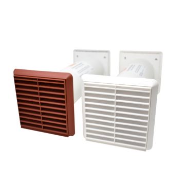
Image disclaimer: For identification and illustration only. It may show a product by another manufacturer and may not depict the exact item described; it is not a statement of any product’s quality, approval or performance. Third-party image and trademark rights belong to their owners. See full notice.
What Is It?
A Moisture Vent (also called a breather vent or desiccant vent) is a passive component installed in sealed AGL enclosures to allow the escape of internal moisture while preventing liquid water ingress. Unlike a pressure valve, which primarily equalises pressure, a moisture vent focuses on removing water vapour that has entered the fixture (e.g., during maintenance or through imperfect seals) or has condensed from temperature cycling. The vent typically incorporates a hydrophobic membrane that allows water vapour (gas) to pass but blocks liquid water. Some vents also include a desiccant material to absorb residual moisture. By preventing condensation on lenses, prisms, and internal optics, the moisture vent ensures that the light output and beam pattern remain unaffected by fogging or water droplets, which is critical for maintaining photometric performance and meeting ICAO/FAA specifications.
Purpose & Function
The moisture vent exists because even a well-sealed AGL fixture will eventually accumulate internal water vapour — from temperature cycling that draws in humid air, or from tiny imperfections in seals over years of service — and if that vapour has nowhere to go, it condenses on the internal optics exactly where it will do the most damage to the fixture's light output. Left unaddressed, that fogging or droplet formation distorts the beam pattern in a way that's invisible from the ground but very real to an approaching pilot relying on that light.
By letting water vapour escape while still blocking liquid water intrusion, the vent solves this without compromising the fixture's overall environmental sealing — a passive, low-maintenance way to protect the photometric performance that ICAO and FAA certification depends on, without requiring active drying equipment or frequent internal inspection.
Where Is It Used?
Moisture vents are used in all sealed AGL fixtures and enclosures where condensation could compromise performance. Key applications include:
- Runway & Taxiway Light Fixtures: Inset and elevated lights with sealed optical chambers.
- Threshold & End Light Housings: Where lens clarity is vital for approach guidance.
- Approach Lighting Fixtures: Barrettes, ALS units, and strobe housings.
- PAPI & VASI Optical Units: Precision visual glide slope indicators where condensation would cause false indications.
- Obstruction Light Housings: Sealed beacons and LED units.
- Isolating Transformer Housings: To prevent internal corrosion and insulation degradation.
- Junction Boxes & Control Panels: To protect terminals and electronic components from moisture.
Installation & Location
The vent fits into a threaded or gasketed port in the fixture housing wall, sized and positioned so it sits above any water ingress point but low enough that the membrane doesn't block the optical path or interfere with the lamp/LED assembly. Orientation matters more than for most fixture hardware: the vent is fitted facing downward or to the side rather than directly upward wherever the fixture geometry allows, so standing water on top of the housing cannot pool against the membrane. Because the vent is a passive, unwired component, no cabling is involved; installation is limited to correct torque on the threaded fitting and a check that the surrounding gasket seats fully so the vent doesn't become an alternate leak path.
How Does It Work?
The moisture vent works on the principle of vapour pressure differential and membrane technology:
- Hydrophobic Membrane: A microporous PTFE (or similar) membrane allows water vapour molecules to pass through while blocking liquid water due to surface tension and pore size.
- Vapour Pressure Gradient: When internal humidity exceeds external humidity, water vapour migrates outward through the membrane, reducing internal moisture content.
- Condensation Prevention: By keeping internal humidity below the dew point (relative to the internal temperature), the vent prevents condensation from forming on cool surfaces like lenses and prisms.
- Desiccant Option: Some vents incorporate a desiccant (e.g., silica gel) that actively absorbs moisture, providing an additional layer of protection.
- IP Rating Maintenance: The vent is designed to maintain the enclosure's IP67/IP68 rating, allowing vapour escape without compromising watertight integrity.
The vent is typically installed in a threaded port on the fixture housing, often at the highest point to allow moisture vapour to rise and escape. It is a passive, maintenance‑free device, though some designs include a replaceable desiccant cartridge.
System Architecture & Control Logic
Unlike the networked components elsewhere in the AGL system, the moisture vent has no electronic control logic of its own — it is a passive part of a fixture or enclosure's mechanical architecture rather than a node on the ALCMS network. Its place in the system is defined by where it sits in the sealed housing: it forms one boundary of the enclosure, alongside the gasket, cable glands, and (in a fixture) the optical window, and it is the only one of those boundaries deliberately designed to let vapour pass while blocking liquid water and dust. When the enclosure heats and cools through its duty cycle, internal air expands and contracts; the vent equalises that pressure difference through the enclosure wall so the seals elsewhere aren't forced to do it, and it lets any moisture that does condense inside migrate back out as vapour. There is no signal or status associated with it — its condition (clear membrane versus clogged or degraded) is checked only through physical or visual inspection during maintenance, not through the monitoring architecture that covers the electronic components in the same enclosure.
Sealed Enclosure / Fixture Housing
Internal air volume, heats and cools through the duty cycle
Moisture Vent (Membrane)
Passes water vapour, blocks liquid water & dust — pressure equalisation
Ambient Atmosphere
Vapour and pressure released outside the housing
How the Membrane Manages Moisture
Internal Humidity Rises
Sealed fixture warms/cools, trapped air humidity increases
Vapour Pressure Gradient Forms
Internal vapour pressure exceeds external — vapour driven outward
Hydrophobic PTFE Membrane
Microporous barrier — selectively permeable by pore size & surface tension
Passes Through Micropores
Molecules small enough to migrate through the membrane freely
Vents to Atmosphere
Internal humidity drops below dew point
Blocked by Surface Tension
Rain, wash-down & wave spray cannot pass the pore structure
Repelled at Membrane Surface
No liquid ingress up to rated water entry pressure
Physical Construction
The vent body is machined from stainless steel (316L), nickel-plated brass, or UV-stabilised polyamide, threaded to match the fixture's mounting port (metric or NPT) and fitted with an O-ring or bonded gasket at the seating face to maintain the enclosure's IP67/IP68 rating once installed. The hydrophobic PTFE membrane is heat-staked or ultrasonically welded across the internal vent channel, backed by a perforated support disc that protects the membrane from mechanical damage during installation while still allowing free vapour passage. Where a desiccant cartridge is included, it sits in a small chamber behind the membrane, accessible for replacement on models designed for periodic servicing, and sealed on non-serviceable models. The external face includes a wrench-flat or knurled grip for hand-tightening into the housing, and the thread sealing relies on either a captive gasket or PTFE tape applied during installation rather than adhesive, so the vent can be removed and replaced without damaging the enclosure port.
Technical Parameters
| Parameter | Typical Value |
|---|---|
| Membrane Material | Hydrophobic PTFE (expanded polytetrafluoroethylene) |
| Housing Material | Stainless steel (316L), brass (nickel‑plated), or UV‑stabilised polyamide |
| Thread Type | Metric (M8, M10, M12) or NPT (1/8", 1/4", 3/8") |
| IP Rating | IP67 / IP68 (when properly installed) |
| Water Vapour Transmission Rate | Typically 100‑500 g/m²/day at 23°C, 85% RH |
| Water Entry Pressure | ≥ 0.5 bar (prevents liquid ingress up to 5m depth) |
| Temperature Range | -40°C to +120°C |
| Chemical Resistance | Resistant to de‑icing fluids, jet fuel, hydraulic fluids, salt spray |
| UV Resistance | Excellent (metal housing), good (UV‑stabilised plastic) |
| Desiccant Option | Silica gel or molecular sieve (replaceable or non‑replaceable) |
| Service Life | Typically 5‑10 years (membrane), desiccant may require periodic replacement |
Applicable Standards
IEC 60529
Degrees of protection provided by enclosures (IP code) — vent maintains IP rating
IEC TS 61827
Characteristics of inset and elevated AGL luminaires (includes environmental sealing requirements)
FAA AC 150/5345-46
General FAA fixture specification; environmental sealing is tested as part of the qualified fixture, vent included
ASTM B117
Salt spray (fog) testing for corrosion resistance
Installation Requirements
Port Sizing & Position
PreparationConfirm the fixture housing's threaded or gasketed port is correctly sized and positioned above any water ingress point but clear of the optical path and lamp/LED assembly.
Orientation Selection
FittingFit the vent facing downward or to the side wherever fixture geometry allows, rather than directly upward, so standing water on top of the housing cannot pool against the membrane.
Torque & Gasket Seating
FittingTorque the threaded fitting to the manufacturer's specification and confirm the surrounding gasket seats fully so the vent doesn't become an alternate leak path.
Pre-Commissioning Sign-off
DocumentationRecord vent orientation and torque value as-built before the fixture housing is closed up.
Testing & Commissioning
Membrane Integrity Check
Pre-InstallationInspect the hydrophobic membrane for damage or contamination before the vent is fitted.
Orientation & Mounting Verification
InstallationConfirm the vent is installed in the manufacturer's specified orientation so it functions as intended.
Seal Integrity Test
InstallationConfirm the vent's gasket forms a watertight seal with the fixture housing once tightened to spec.
Pressure Equalisation Check
Final AcceptanceConfirm the vent equalises internal pressure without allowing water ingress, using a controlled water-spray or pressure test where applicable.
Desiccant Condition Check
Pre-InstallationConfirm any desiccant element is fresh and correctly seated before the vent is fitted.
Documentation & As-Built Sign-off
Final AcceptanceRecord vent type, orientation, and installation checks in the commissioning dossier for handover.
Inspection & Maintenance
Membrane Inspection & Cleaning
Semi-annualCheck the vent membrane for clogging from dust, insects, or contaminants and clean to restore airflow.
Desiccant Check
AnnualWhere fitted, check desiccant saturation and replace to maintain effective moisture control.
Orientation & Mounting Check
AnnualConfirm the vent remains correctly oriented as installed, since incorrect orientation compromises its function.
Housing Corrosion Inspection
AnnualCheck the metal housing for corrosion, particularly at the mounting interface and any exposed fasteners.
Common Field Issues
Membrane Clogging with Contaminants
In dusty or industrial environments, the hydrophobic membrane can become clogged with dust, salt, or oil aerosols, reducing vapour transmission. This can lead to moisture build‑up and condensation. Regular inspection and cleaning (or replacement) of the vent is recommended.
Desiccant Saturation (if fitted)
Vents with desiccant cartridges have a finite absorption capacity. Once saturated, they no longer absorb moisture, and the vent may become ineffective. Desiccant should be replaced periodically based on humidity exposure and inspection.
Improper Installation Orientation
Moisture vents should be installed with the vent opening facing downward or sideways to prevent water pooling and to allow vapour to escape. Incorrect orientation can lead to water ingress or reduced vapour transmission. Always follow the manufacturer's installation instructions.
Corrosion of Metal Housing
In coastal or marine environments, metal vent housings can corrode if not made of stainless steel or adequately plated. Use stainless steel vents in such conditions.
Damage from High‑Pressure Water Jets
During runway washing or de‑icing operations, high‑pressure water jets can force liquid water through the membrane if the pressure exceeds the water entry pressure rating. Protect vents with splash guards or install them in locations not directly exposed to high‑pressure jets.
Troubleshooting Guide
Condensation or Fogging Found Inside the Enclosure
Water Found Pooling Inside the Enclosure Near the Vent
Metal Vent Housing Showing Corrosion
Water Ingress Following Runway Washing or De-icing
Failure Modes & Root Causes
Membrane / Desiccant Saturation
Incorrect Installation Orientation
Housing Corrosion
Water Entry Pressure Exceedance
Safety & Operational Notes
Electrical Isolation Before Opening the Enclosure
Electrical SafetyDe-energise and lock out the circuit the enclosure belongs to and verify zero energy before removing or servicing a moisture vent fitted to a fixture, base can, or cabinet, since accessing the vent usually means opening a live enclosure.
FOD Control
OperationalKeep the vent, its retaining hardware, and any desiccant cartridge accounted for at all times during servicing; these are small parts that are easily dropped and left behind inside the enclosure or on the pavement.
Confirm Correct Orientation and Seal on Refit
ComplianceRefit the vent in its correct orientation with the hydrophobic membrane properly seated, since an incorrectly fitted vent can let liquid water in rather than just venting vapour, defeating its purpose.
Desiccant Cartridge Handling
Personnel SafetyWhere the vent incorporates a replaceable desiccant cartridge, handle it per the manufacturer's guidance and dispose of spent cartridges appropriately; avoid contact with eyes if the desiccant material is disturbed or damaged.
Restore to Compliant State
ComplianceConfirm the enclosure reseals correctly around the vent and re-energise only once the housing is fully closed up, to avoid re-introducing the moisture the vent is meant to manage.
Engineering & Expert Notes
Orientation is the Single Most Common Installation Error
InstallationA moisture vent installed facing upward instead of downward or sideways can allow standing water to pool directly against the membrane, eventually forcing liquid through under gravity alone even at pressures well below the rated water entry pressure. Verify orientation against the manufacturer's diagram as a specific commissioning checklist item, since this single detail accounts for a disproportionate share of vent-related moisture ingress.
Membrane Clogging Reduces Function Long Before It's Visible
MaintenanceA hydrophobic membrane can lose significant vapour transmission capacity from a light film of dust, salt aerosol, or oil residue well before it looks visibly blocked. Test actual vapour transmission or pressure equalisation response periodically rather than relying on a visual "looks clean" check, particularly at sites with heavy de-icing fluid or airborne particulate exposure.
High-Pressure Washing Can Defeat a Correctly Rated Vent
OperationalRunway or fixture washing with pressure-washing equipment can exceed a moisture vent's rated water entry pressure even though the vent performs correctly under normal rain and weather exposure. Site vents away from direct pressure-washer contact where possible, or fit a splash guard, rather than assuming the standard IP rating covers deliberate high-pressure cleaning.
Desiccant Saturation Fails Silently
DurabilityA saturated desiccant cartridge doesn't announce itself — the vent continues to look intact and installed correctly while providing essentially no additional moisture absorption. Replace desiccant on a defined schedule based on known humidity exposure rather than waiting for a fogging complaint to trigger replacement.
Vent Failure is Usually Diagnosed by Its Symptom, Not Itself
TroubleshootingInternal fogging or condensation is almost always traced back to the moisture vent or a general seal failure elsewhere on the enclosure, so when fogging appears, check both the vent's condition and the fixture's other seals together rather than assuming the vent is automatically at fault or automatically innocent.
Size the Vent to the Enclosure's Actual Thermal Cycling, Not a Generic Spec
DesignAn enclosure that experiences large day-night temperature swings pumps more moist air in and out through its vent than a more thermally stable one, so a vent sized adequately for one site's climate can be undersized for a hotter, more variable one. Match vent sizing to the specific fixture's expected thermal cycling range rather than defaulting to a single standard part across all sites.
Related Components
Frequently Asked Questions
Short answers about AGL moisture vents: how they work, specifications, orientation, standards and maintenance.
Q1What is a moisture vent in an AGL fixture?
A moisture vent, also called a breather vent or desiccant vent, is a passive component in sealed AGL enclosures that lets internal water vapour escape while blocking liquid water. It uses a hydrophobic membrane, and some designs add a desiccant to absorb residual moisture.
Q2Why do sealed AGL fixtures need a moisture vent?
Even a well-sealed fixture accumulates water vapour over time, from temperature cycling that draws in humid air or from tiny seal imperfections. If the vapour has nowhere to go it condenses on lenses and prisms, distorting the beam pattern in a way that is invisible from the ground but real to an approaching pilot.
Q3How does a moisture vent work?
A microporous PTFE membrane passes water vapour but blocks liquid water because of surface tension and pore size. When internal humidity exceeds external humidity, vapour migrates outward, keeping internal humidity below the dew point so condensation does not form. The vent is designed to maintain the enclosure's IP67/IP68 rating.
Q4What is the difference between a moisture vent and a pressure valve?
A pressure valve mainly equalises pressure. A moisture vent focuses on removing water vapour that has entered the fixture, for example during maintenance or through imperfect seals, or that has condensed from temperature cycling.
Q5Where are moisture vents used?
They are used in sealed runway and taxiway fixtures, threshold and end light housings, approach lighting fixtures, PAPI and VASI optical units, obstruction light housings, isolating transformer housings, and junction boxes and control panels.
Q6What are typical moisture vent specifications?
Typical vents use a hydrophobic PTFE membrane in a 316L stainless steel, nickel-plated brass or UV-stabilised polyamide housing, with metric (M8, M10, M12) or NPT (1/8, 1/4, 3/8 inch) threads. Water entry pressure is at least 0.5 bar, the temperature range is -40°C to +120°C, and membrane service life is typically 5 to 10 years.
Q7How should a moisture vent be oriented and mounted?
It fits into a threaded or gasketed port in the housing wall, positioned above any water ingress point without blocking the optical path. It should face downward or to the side to prevent water pooling and let vapour escape. Incorrect orientation compromises its function, so check it on every refit.
Q8Which standards apply to moisture vents?
The main references are IEC 60529 (IP code), IEC TS 61827 (inset and elevated AGL luminaires, including environmental sealing), FAA AC 150/5345-46 (sealing is tested as part of the qualified fixture, vent included) and ASTM B117 (salt spray testing). Always verify the current edition.
Q9Does a moisture vent need maintenance?
It is a passive, largely maintenance-free device, but typical checks are semi-annual for membrane inspection and cleaning, and annual for desiccant saturation (where fitted), orientation and mounting, and housing corrosion. Your airport's approved maintenance programme takes precedence.
Q10What are the common moisture vent problems?
The common issues are a membrane clogged by dust, salt or oil aerosols, saturated desiccant, incorrect orientation, corrosion of metal housings in coastal or marine environments (use stainless steel there), and high-pressure water jets from runway washing or de-icing forcing water through the membrane above its entry pressure rating.
Go Beyond the Component. Understand the Complete AGL System.
You have explored the component. Now understand how it works within the complete Airfield Ground Lighting system.
Learn AGL from fundamentals to design, installation, testing, photometry, commissioning, maintenance and troubleshooting through structured technical training at Precision AGL Academy.
Build practical knowledge. Understand the circuit. Read the standards. Troubleshoot with confidence.
Your next step in AGL starts here.
Need expert guidance on moisture vent selection, installation, or maintenance for AGL fixtures?
Precision AGL Academy provides advice on vent types, membrane selection, and field best practices to keep your fixtures fog‑free and reliable.
Follow the Academy
Important Notice, Disclaimer & Limitation of Liability
Please read before relying on any content on this page.
- Purpose and intended users. This page on Moisture Vent is an independent educational and informational reference for competent, suitably trained and authorised airfield ground lighting (AGL) and aerodrome electrical personnel. It is not professional engineering, legal or regulatory advice, and using it does not create any professional or client relationship.
- Safety. Work on series circuits, constant current regulators (CCRs), isolating transformers, cables, connectors and lighting equipment can be fatal. Always apply the aerodrome’s permit-to-work and isolation/LOTO procedures, prove dead, use correctly rated instruments and PPE, and follow the manufacturer’s instructions. Nothing here authorises work on live equipment or the bypassing of any safety device or interlock.
- Aviation operations. Nothing here authorises installation, modification, energisation, adjustment, return to service, a change of operating category (CAT I/II/III), a NOTAM or any aerodrome certification or approval decision. These rest with the aerodrome operator, the air navigation service provider and the competent regulator.
- Specifications, ratings and typical values. Descriptions, parameters, ratings, dimensions, photometric values, wattages, service lives, maintenance tasks and intervals, failure modes, certifications (for example CE, FCC, UL or IEC marks) and part or type designations are general, typical and indicative. They may not match any particular product, make, model or version, and they are not a datasheet, design, specification, selection, sizing, procurement or acceptance criterion. The manufacturer’s current documents, the approved design and the project specification prevail.
- Standards and regulations. References to ICAO, FAA, IEC, IEEE, ISO, BIS, DGCA and other standards are paraphrased summaries for orientation only. They may be incomplete or out of date, and standards are revised from time to time. Consult the current official editions. Following this content does not guarantee compliance with any law, standard or regulatory approval, and the regulator’s requirements always prevail.
- No warranty. Content is provided “as is” and “as available”, without warranty of any kind, express or implied, including accuracy, completeness, currency or fitness for a particular purpose. Real installations differ in design, equipment make and model, age and condition.
- Limitation of liability. To the fullest extent permitted by applicable law, Precision AGL Academy, Precision AGL Solutions and their owners, authors and contributors are not liable for any injury, death, loss, damage, downtime, penalty or regulatory consequence, whether direct or indirect, arising from the use of, reliance on, or inability to use this content. Nothing in this notice excludes or limits any liability that cannot lawfully be excluded or limited.
- Independence, brands and no endorsement. This is an independent publication. It is not affiliated with, sponsored by or endorsed by ICAO, the FAA, the IEC, DGCA, AAI, any airport, regulator, supplier or equipment manufacturer. Third-party names, product designations, standard designations and trademarks (including Megger®, Siemens, Eaton, Crouse-Hinds, ADB SAFEGATE, Fluke, ABB and Honeywell) belong to their respective owners and are used only for identification and description. Mention of a brand, product or supplier is not a recommendation, and we do not sell, supply or quote for any component described.
- Images and third-party content. Images and illustrations are shown to help identify the type of component. They may show products of various manufacturers, may not depict the exact item described, and are not a statement about any product’s quality, approval or performance. Copyright and trademarks in third-party images, logos and photographs belong to their respective owners and are not claimed as ours. If you are a rights holder and want an image removed, replaced or credited, email precisionaglsolutions@gmail.com with the page address and we will act promptly.
- Training and services. Mentions of training, courses, consultation, advice, selection, installation, calibration or other support, including the “Learn…Certify” pathway, describe learning stages and are not an offer, quotation, tender or promise of any result. Contacting us or our replying creates no engagement or duty of care; an engagement exists only under a written agreement. We are not a regulator or certification body, and completing any course or reading this content is not a certification, accreditation or authorisation to work on any aerodrome.
- Copyright, privacy and corrections. © 2026 Precision AGL Academy. All rights reserved. Text, structure, compilations and diagrams may be viewed for personal reference and internal training only; any other copying, republication or commercial use needs our written permission. If you email, telephone or message us, we use your details only to respond and handle your matter, in line with applicable Indian law including the Digital Personal Data Protection Act, 2023; please do not send confidential or security-sensitive information. To display this page your browser requests fonts, icons and images from third-party servers, which receive your IP address and browser details under their own policies. Content is reviewed periodically with no obligation to update. To report an error, safety concern or rights issue, write to precisionaglsolutions@gmail.com.