Master Control Panel
The central command console for the entire airfield lighting system. The Master Control Panel provides comprehensive, unified control and monitoring of all AGL circuits, CCRs, and auxiliary systems. It serves as the primary operator interface in the control tower or airfield operations room, integrating with the ALCMS to deliver real‑time status, advanced alarm management, and secure, role‑based control.
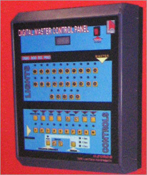
Image disclaimer: For identification and illustration only. It may show a product by another manufacturer and may not depict the exact item described; it is not a statement of any product’s quality, approval or performance. Third-party image and trademark rights belong to their owners. See full notice.
What Is It?
The Master Control Panel (MCP) is the primary human‑machine interface for the airfield lighting control system. Typically installed in the air traffic control tower or the central airfield operations room, the MCP provides a consolidated, intuitive dashboard for monitoring and controlling all aspects of the airfield ground lighting infrastructure. Unlike simpler remote or auxiliary panels, the Master Control Panel is a high‑end, feature‑rich console that offers:
- Unified System View: A comprehensive graphical representation of the entire airfield, showing the status of every runway, taxiway, approach lighting system, and obstruction light in real‑time.
- Integrated Control: Centralised control of all circuits, brightness steps, CCRs, and auxiliary equipment (e.g., stop bars, guidance signs) from a single interface.
- Advanced Alarm Management: Sophisticated alarm prioritisation, suppression, and logging, with clear visual and audible alerts to help operators respond efficiently to faults.
- Role‑Based Access Control: Secure authentication (passwords, biometrics, or smart cards) with granular permissions to ensure that only authorised personnel can execute critical commands.
- Historical Data & Reporting: Built‑in data logging and trend analysis tools for compliance reporting, maintenance planning, and post‑incident investigation.
- Redundancy & Failover: Designed for high availability, often with dual power supplies, redundant network connections, and hot‑standby hardware to ensure continuous operation.
The Master Control Panel is the nerve centre of the AGL system, integrating with the ALCMS server, PLCs, remote I/O, and field devices via redundant communication links. It is typically a large‑format console with multiple high‑resolution touchscreens or a wide‑screen display, accompanied by a physical control desk with pushbuttons, rotary switches, and status indicators for critical functions.
Purpose & Function
The Master Control Panel exists to give a single operator the situational awareness and command authority needed to run an entire airfield's lighting from one seat, rather than requiring them to correlate information from dozens of separate subsystem displays under time pressure. When conditions are changing fast — deteriorating visibility, an unplanned runway configuration change ahead of an arrival — consolidating that decision-making into one interface is what lets a response happen in seconds rather than minutes.
Its emphasis on redundancy and failover reflects what's actually at stake if this panel goes down: as the nerve centre of the entire AGL system, an MCP outage doesn't just inconvenience one operator, it can remove central visibility and control over runway, taxiway, and approach lighting airfield-wide, which is why hot-standby hardware and dual power supplies are standard requirements rather than optional extras for this specific role.
Where Is It Used?
The Master Control Panel is deployed in all airfields that require centralised, high‑reliability control of AGL systems, including:
- Air Traffic Control Towers: Providing tower controllers with a clear, real‑time view of all runway and taxiway lighting, enabling rapid adjustments for changing weather, traffic, and operational conditions.
- Airfield Operations Rooms: Serving as the primary control point for operations staff to manage lighting configurations, coordinate with ATC, and respond to emergencies.
- Airport Control Centres: Integrated into the broader airport management system, allowing unified control of AGL alongside other airport utilities (e.g., power, HVAC, security).
- Military Air Bases: Supporting mission‑critical operations with enhanced security features, redundant hardware, and hardened interfaces.
- Major International Airports: Handling large, complex AGL networks with multiple runways, taxiways, and approach lighting systems, requiring comprehensive monitoring and control capabilities.
Installation & Location
The Master Control Panel is installed in the ATC tower cab or an adjacent equipment room, and in larger airports' integrated operations centres, positioned so controllers have direct sightline or close proximity to the runway environment it commands. It's rack- or console-mounted with its network, power, and hot-standby links terminated into the facility's structured cabling, tied back to the CCRs and field control cabinets it oversees via the ALCMS network rather than direct field wiring. Redundant units are sited far enough apart (separate racks, or separate rooms on critical installations) that a single local fault, fire, or power loss can't take out both the primary and standby panel together, and access is restricted to authorised operations and maintenance staff given the panel's command authority over the entire lighting network.
How Does It Work?
The Master Control Panel operates as the central interface between the operator and the AGL system, performing a wide range of functions to ensure safe, efficient airfield lighting management:
- Real‑Time Data Acquisition: The MCP continuously receives status data from the ALCMS server and/or field devices via redundant communication links (Ethernet, fiber, serial). This data includes circuit states, current levels, brightness steps, alarm conditions, and device health.
- Graphical User Interface: The panel displays a dynamic, geospatial map of the airfield, with colour‑coded icons indicating the status of each lighting element (e.g., green = ON, red = FAULT, amber = STANDBY). Operators can zoom, pan, and click on any element to view detailed information and access control options.
- Command Execution: Operators issue commands (e.g., turn on Runway 09, set brightness to Step 4) through touchscreen gestures, mouse clicks, or physical switches. The MCP validates the command against security policies, interlock rules, and operational constraints, then transmits it to the ALCMS or directly to field devices for execution.
- Alarm Management: The MCP receives and processes alarms from the ALCMS, categorising them by severity (critical, major, minor, warning). Alarms are displayed in a prioritised list with audible and visual cues. Operators can acknowledge, silence, and add comments to alarms, and the MCP logs all actions for audit purposes.
- Logging & Reporting: The MCP logs all operator actions, system events, and alarm activities to a historian database. This data can be used for compliance reporting (e.g., FAA/ICAO logs), trend analysis, and maintenance planning.
- User Authentication & Access Control: The MCP enforces role‑based access control (RBAC) with multiple user levels (e.g., operator, supervisor, administrator). Login is secured via password, smart card, or biometric authentication. Permissions are granular, controlling access to specific circuits, functions, and system settings.
- Redundancy & Failover: In critical installations, the MCP is configured with redundant hardware (dual power supplies, redundant network interfaces) and software failover (hot‑standby MCP). If the primary MCP fails, the backup automatically takes over, ensuring uninterrupted control.
The MCP is typically built on a high‑performance industrial PC or workstation, running a dedicated ALCMS client application. It communicates with the ALCMS server using standard protocols (OPC UA, Modbus TCP, IEC 61850) and is designed for 24/7/365 operation in a control room environment.
System Architecture & Control Logic
The Master Control Panel sits at the very top of the AGL control hierarchy — every command that eventually reaches a CCR and, through it, a series circuit and its fixtures, can originate here. Rather than replacing the loop-level control architecture used throughout the rest of the system, the MCP is the human-operated entry point into it: an operator's command is validated against security policy, interlock rules, and operational constraints before being handed to the ALCMS server, which then distributes it down through PLCs and remote I/O to the CCRs and field devices that actually switch and dim the lighting.
Because an MCP outage would remove central visibility and control over the entire airfield rather than just one circuit, its architecture is built around redundancy from the top down — dual power supplies, redundant network links, and hot-standby hardware mean command authority itself has no single point of failure, on top of the loop-level fault tolerance already built into the CCR and series-circuit layer beneath it.
Operator → MCP (validation) → ALCMS/PLCs → CCR → Series Circuit → Fixture (hot-standby failover)
Command Validation With Hot-Standby Failover
Physical Construction
The panel is built either as a console desk with integrated high-brightness touchscreens set into an angled work surface, or as a wall/rack-mounted industrial workstation chassis housing a large-format display, depending on the tower or operations-room layout it serves. The computing hardware — high-performance processor, RAM, and SSD storage — is mounted in a separate rack-mount chassis or an integrated console compartment rather than behind the display itself, simplifying servicing without disturbing the operator-facing screens, and dual redundant power supplies are fed from independent circuits so a single power-path fault does not take the panel offline. Network and communication cabling is terminated into the facility's structured cabling system at the rear of the console or an adjacent equipment rack, keeping cable runs and connectors out of the operator's reach, and the enclosure is rated IP20 for indoor control-room use only, relying on the facility's own environmental control rather than a sealed outdoor-rated housing. Where hot-standby redundancy is specified, the primary and backup hardware are built as physically separate units — sometimes in separate racks or rooms — so a local fault, fire, or power loss affecting one cannot also disable the other.
Technical Parameters
| Parameter | Typical Value |
|---|---|
| Form Factor | Console desk with integrated screens, or wall‑mounted industrial workstation |
| Display Configuration | Dual or triple 24" to 32" high‑brightness touchscreens (or single large‑format 55" display) |
| Resolution | 1920×1080 (Full HD) to 3840×2160 (4K UHD) |
| Processor | Intel Core i7/i9, Xeon, or AMD Ryzen 7/9 (high‑performance multi‑core) |
| Memory (RAM) | 16GB to 64GB (for handling large airfield datasets) |
| Storage | 512GB to 2TB SSD (for fast boot and application performance) |
| Operating System | Windows 10/11 Pro, Windows Server, or Linux (custom deployments) |
| Communication Interfaces | 2 x 1G Ethernet (redundant), optional fiber SFP, serial (RS‑232/485) |
| Protocols Supported | OPC UA, Modbus TCP/RTU, Profinet, Ethernet/IP, IEC 61850, BACnet |
| Power Supply | 120/230 VAC ±10%, 50/60 Hz, with dual redundant power supplies |
| Power Consumption | 150‑400 W (depending on display size and processing load) |
| Operating Temperature | 10°C to 40°C (standard office/control room environment) |
| Storage Temperature | -20°C to 60°C |
| Protection Class | IP20 (indoor use only) |
| Security Features | Role‑based access control, audit logging, encryption (TLS/SSL), biometric authentication (optional) |
| Redundancy | Hot‑standby (active/backup) with automatic failover |
| Certifications | CE, FCC, UL, IEC 61000‑6‑2 (EMC immunity), FAA AC 150/5345‑56 |
Electrical Requirements
| Requirement | Typical Value |
|---|---|
| Circuit Type | Mains-powered control/HMI equipment — not part of the airfield series circuit |
| Power Supply | 120/230VAC ±10%, 50/60Hz, dual redundant power supplies |
| Power Consumption | 150–400W depending on display size and processing load |
| Cable Type | IEC C13/C14 mains cord; shielded Ethernet/serial for data |
| Backup Power | UPS-backed for ride-through during mains interruption |
| Earthing/Grounding | Chassis bonded to the building/control-room earth |
| Fault Protection | Internal fusing, with hot-standby failover to a backup unit on fault |
| Protection Class | IP20 (indoor use only) |
Applicable Standards
FAA AC 150/5345‑56
Specification for ALCMS — includes requirements for master control panels
ICAO Annex 14
Requirements for AGL control and monitoring — operator interface guidelines
IEC 61850
Communication networks and systems for power utility automation (used for data exchange)
ISO 9241
Ergonomics of human‑system interaction — user interface design principles
Installation Requirements
Rack/Console Mounting Position
MechanicalMount in the ATC tower cab or equipment room, positioned so controllers have direct sightline or close proximity to the runway environment it commands.
Structured Cabling Termination
ElectricalTerminate network, power, and hot-standby links into the facility's structured cabling before configuration.
Redundant Unit Separation
CivilSite redundant units far enough apart — separate racks, or separate rooms on critical installations — to avoid a common-mode failure taking out both.
ALCMS Network Registration
NetworkRegister the panel on the ALCMS network and confirm it can reach the CCRs and field control cabinets it oversees before commissioning.
Access Control Configuration
SoftwareConfigure user access levels and controls before the panel is placed in service.
Pre-Commissioning Sign-off
DocumentationRecord mounting location, cabling terminations, and access configuration as-built before failover testing begins.
Testing & Commissioning
Protocol Link Verification
EnergisationConfirm communication with every connected CCR, remote panel, and field device, checking that live values and controls report and act correctly.
Failover Test
Final AcceptanceSimulate a primary hardware or power fault and confirm the panel fails over to redundant hardware or supply without loss of control.
Touchscreen & Display Calibration Check
InstallationCalibrate the touchscreen and verify display readability and touch accuracy across the full screen area.
Access Control & Function Test
Final AcceptanceConfirm operator login levels and control permissions match the site's operating procedure, and that critical actions require the correct authorisation.
Redundant Power Supply Test
Pre-EnergisationConfirm both power supplies share load correctly and that the panel continues operating uninterrupted on loss of either single supply.
Documentation & As-Built Sign-off
Final AcceptanceRecord protocol, failover, and access control test results in the commissioning dossier.
Inspection & Maintenance
Failover Test
AnnualTrigger a controlled switchover to the hot-standby unit to confirm automatic failover completes without loss of operator visibility.
Touchscreen & Display Calibration
Semi-annualCheck touchscreen response accuracy and display brightness/colour, especially on control-room displays used continuously in shift work.
Protocol Link Verification
Semi-annualConfirm OPC UA, Modbus, Profinet, and IEC 61850 links to downstream systems are current and reporting without errors.
Access Control & Audit Review
AnnualReview role-based access accounts and audit logs, and verify biometric authentication (where fitted) is functioning correctly.
OS & Application Patching
QuarterlyApply validated OS and application security patches on a controlled maintenance window that doesn't interrupt live operator use.
Redundant Power Supply Check
Semi-annualRemove each dual redundant power supply in turn to confirm the panel continues operating without interruption.
Storage & Performance Health Check
Semi-annualCheck SSD health and system responsiveness under typical operator load to catch degradation before it affects command response times.
Ventilation & Thermal Check
AnnualClean intake vents and confirm cooling is adequate for the console's processing load, since dust buildup is a common cause of thermal throttling.
Common Field Issues
Network Connectivity Loss
If the MCP loses connection to the ALCMS server or field devices, it cannot display real‑time data or issue commands. Use redundant network interfaces and dedicated network infrastructure (VLAN) to minimise risk. Implement automatic reconnection and clear "loss of communication" alarms.
Performance Degradation
Large airfield maps with thousands of data points can cause performance lag on under‑specified hardware. Use a dedicated GPU, sufficient RAM, and an SSD. Optimise the software to handle large datasets efficiently (e.g., level‑of‑detail rendering).
Display Burn‑in / Image Retention
Static elements on the display (e.g., airfield map) can cause burn‑in on some screen types. Use screen savers, periodic dimming, or pixel‑shifting technology. Consider using OLED or high‑quality IPS panels.
Software Bugs or Crashes
ALCMS client software can occasionally crash or exhibit bugs. Ensure robust error handling, automatic restart, and maintain a hot‑standby MCP to take over if the primary fails. Test software updates thoroughly before deployment.
Inadequate User Training
The complexity of the MCP requires comprehensive operator training. Inadequate training can lead to errors, missed alarms, or slow response times. Provide regular training sessions, simulation exercises, and maintain up‑to‑date user manuals.
Cybersecurity Vulnerabilities
MCPs are potential targets for cyberattacks. Implement strong password policies, use antivirus and firewall protection, keep the OS and software patched, and restrict physical access to the console. Conduct regular security audits and penetration tests.
Alarm Fatigue
Excessive nuisance alarms can desensitise operators. Implement alarm suppression, filtering, and rationalisation to ensure only critical alarms are presented. Regularly review alarm settings with operations staff.
Troubleshooting Guide
MCP Loses Real-Time Data or Cannot Issue Commands
Display Lags or Slow to Update on Large Airfield Maps
Ghost Image or Burn-in Visible on the Display
ALCMS Client Software Crashes or Freezes
Operator Errors or Missed Alarms During Shift
Suspected Unauthorised Access to the MCP Console
Operators Desensitised to Alarms / Missing Critical Alerts
Failure Modes & Root Causes
Loss of Connectivity to ALCMS or Field Devices
Display Performance Degradation
Client Software Instability
Unauthorised Console Access
Alarm Fatigue
Safety & Operational Notes
Verify State Before Issuing Commands
OperationalConfirm the displayed airfield state is current before issuing a control command from the MCP, since a command sent against stale or lagging data can act on the wrong circuit or setting.
Confirm Redundant Path Before Maintenance
OperationalVerify a backup console or network path can maintain monitoring and control before taking the MCP offline for service, so the operator is never without visibility of the lighting system.
Isolate Before Hardware Work
Electrical SafetyPower down and unplug the console before opening it for hardware service, and use anti-static precautions when handling internal components.
UPS Backup for Operator Visibility
OperationalConfirm the MCP is on UPS-backed power, since it is the primary console for the entire lighting system and losing its display during a mains interruption removes control exactly when field conditions may be changing.
Function-Test After Software Updates
VerificationRun a full command-and-control function test after any client software update or hardware change before relying on the MCP for live operations.
Restrict Access
OperationalKeep operator access to the MCP restricted to authorised personnel; it is the highest-authority control point for the entire airfield lighting system.
Coordinate Before Planned Downtime
OperationalNotify the tower or airfield operations before planned maintenance that will interrupt the MCP's monitoring or control function, so alternate arrangements are in place for the outage window.
Restore to Compliant State
ComplianceConfirm live data, alarm annunciation, and full command function are working correctly before returning the MCP to unattended service after any maintenance.
Engineering & Expert Notes
Display Latency Can Look Like a Live State When It Isn't
TroubleshootingA polling delay between field CCRs and the MCP display can leave an operator issuing a command based on a state that changed seconds ago, which matters most during rapid intensity-step changes for weather. Check the actual poll/refresh interval against the operational tempo required, not just whether the display eventually updates correctly.
Operator Habits Drift Once a Backup Console Is Rarely Used
OperationalA backup console that's technically functional but almost never actually operated in practice tends to have operators who are slower and less confident using it when the primary MCP genuinely fails. Schedule periodic live handover drills on the backup path, not just a technical connectivity test, so the fallback is actually usable under pressure.
Access Restriction Needs Auditing, Not Just Configuration
CybersecurityAn MCP configured with restricted access at commissioning can accumulate shared logins, orphaned accounts from staff who've since left, or a generic "operator" credential used by everyone over the years. Periodically audit who can actually issue commands against who should be able to, rather than assuming the original access model still holds.
Test Software Updates on a Non-Critical Function First
MaintenanceA client software update that changes how alarms are annunciated or how commands are queued can introduce a subtle behavioural difference that a basic function test doesn't surface. Where practical, exercise the updated software through a full simulated fault/alarm scenario before trusting it in live unattended operation, not just a command-and-response check.
Alarm Fatigue Is a Real Operational Risk at This Console
DesignAn MCP that surfaces every minor field deviation as an alarm with equal visual weight trains operators to start filtering out alerts by habit, which is exactly when a genuine critical alarm gets missed. Review alarm prioritisation and nuisance-alarm rates periodically, since the console's usefulness depends as much on signal-to-noise as on raw data accuracy.
UPS Runtime Assumptions Age With the Battery, Not Just the Load
ReliabilityA UPS sized to carry the MCP through a typical outage at commissioning can fall well short of that runtime years later purely from battery ageing, independent of any change in the console's power draw. Verify actual UPS runtime periodically rather than relying on the original sizing calculation as still valid indefinitely.
Frequently Asked Questions
Short answers about master control panels (MCP): function, location, redundancy, standards and maintenance.
Q1What is a Master Control Panel in airfield lighting?
The Master Control Panel (MCP) is the main human-machine interface for the airfield lighting control system, usually installed in the control tower or airfield operations room, giving a unified view and control of the airfield lighting.
Q2Where is the MCP installed?
In air traffic control towers, airfield operations rooms and airport control centres, and on military air bases where enhanced security and redundancy are needed.
Q3What does an MCP display and control?
A dynamic graphical map of the airfield with colour-coded icons for each lighting element, for example green for on, red for fault and amber for standby. Operators can switch circuits and set brightness steps by touchscreen, mouse or physical switches.
Q4How does the MCP connect to the airfield?
It receives status data from the ALCMS server and or field devices over redundant communication links such as Ethernet, fibre or serial, and validates commands against security policies and interlock rules before sending them.
Q5Why is redundancy important for an MCP?
The MCP is the controller's main way of operating airfield lighting, so a failure must not leave the airfield uncontrolled. Hot-standby units with automatic failover are tested regularly to confirm the switchover works.
Q6Which standards apply to master control panels?
The main references are FAA AC 150/5345-56 (ALCMS), ICAO Annex 14, IEC 61850 for data exchange and ISO 9241 for ergonomic interface design.
Q7How often should an MCP be maintained?
An annual failover test, and semi-annual touchscreen and display calibration checks and protocol link verification for OPC UA, Modbus, Profinet and IEC 61850 connections.
Q8What are the common problems with master control panels?
Network connectivity loss to the ALCMS server or field devices, performance lag with large airfield maps, display burn-in from static elements, and software bugs or crashes.
Related Components
Go Beyond the Component. Understand the Complete AGL System.
You have explored the component. Now understand how it works within the complete Airfield Ground Lighting system.
Learn AGL from fundamentals to design, installation, testing, photometry, commissioning, maintenance and troubleshooting through structured technical training at Precision AGL Academy.
Build practical knowledge. Understand the circuit. Read the standards. Troubleshoot with confidence.
Your next step in AGL starts here.
Need expert guidance on Master Control Panel selection, configuration, or integration with your ALCMS?
Precision AGL Academy provides advice on display sizing, user interface design, redundancy planning, and operator training for effective AGL system control.
Follow the Academy
Important Notice, Disclaimer & Limitation of Liability
Please read before relying on any content on this page.
- Purpose and intended users. This page on Master Control Panel is an independent educational and informational reference for competent, suitably trained and authorised airfield ground lighting (AGL) and aerodrome electrical personnel. It is not professional engineering, legal or regulatory advice, and using it does not create any professional or client relationship.
- Safety. Work on series circuits, constant current regulators (CCRs), isolating transformers, cables, connectors and lighting equipment can be fatal. Always apply the aerodrome’s permit-to-work and isolation/LOTO procedures, prove dead, use correctly rated instruments and PPE, and follow the manufacturer’s instructions. Nothing here authorises work on live equipment or the bypassing of any safety device or interlock.
- Aviation operations. Nothing here authorises installation, modification, energisation, adjustment, return to service, a change of operating category (CAT I/II/III), a NOTAM or any aerodrome certification or approval decision. These rest with the aerodrome operator, the air navigation service provider and the competent regulator.
- Specifications, ratings and typical values. Descriptions, parameters, ratings, dimensions, photometric values, wattages, service lives, maintenance tasks and intervals, failure modes, certifications (for example CE, FCC, UL or IEC marks) and part or type designations are general, typical and indicative. They may not match any particular product, make, model or version, and they are not a datasheet, design, specification, selection, sizing, procurement or acceptance criterion. The manufacturer’s current documents, the approved design and the project specification prevail.
- Standards and regulations. References to ICAO, FAA, IEC, IEEE, ISO, BIS, DGCA and other standards are paraphrased summaries for orientation only. They may be incomplete or out of date, and standards are revised from time to time. Consult the current official editions. Following this content does not guarantee compliance with any law, standard or regulatory approval, and the regulator’s requirements always prevail.
- No warranty. Content is provided “as is” and “as available”, without warranty of any kind, express or implied, including accuracy, completeness, currency or fitness for a particular purpose. Real installations differ in design, equipment make and model, age and condition.
- Limitation of liability. To the fullest extent permitted by applicable law, Precision AGL Academy, Precision AGL Solutions and their owners, authors and contributors are not liable for any injury, death, loss, damage, downtime, penalty or regulatory consequence, whether direct or indirect, arising from the use of, reliance on, or inability to use this content. Nothing in this notice excludes or limits any liability that cannot lawfully be excluded or limited.
- Independence, brands and no endorsement. This is an independent publication. It is not affiliated with, sponsored by or endorsed by ICAO, the FAA, the IEC, DGCA, AAI, any airport, regulator, supplier or equipment manufacturer. Third-party names, product designations, standard designations and trademarks (including Megger®, Siemens, Eaton, Crouse-Hinds, ADB SAFEGATE, Fluke, ABB and Honeywell) belong to their respective owners and are used only for identification and description. Mention of a brand, product or supplier is not a recommendation, and we do not sell, supply or quote for any component described.
- Images and third-party content. Images and illustrations are shown to help identify the type of component. They may show products of various manufacturers, may not depict the exact item described, and are not a statement about any product’s quality, approval or performance. Copyright and trademarks in third-party images, logos and photographs belong to their respective owners and are not claimed as ours. If you are a rights holder and want an image removed, replaced or credited, email precisionaglsolutions@gmail.com with the page address and we will act promptly.
- Training and services. Mentions of training, courses, consultation, advice, selection, installation, calibration or other support, including the “Learn…Certify” pathway, describe learning stages and are not an offer, quotation, tender or promise of any result. Contacting us or our replying creates no engagement or duty of care; an engagement exists only under a written agreement. We are not a regulator or certification body, and completing any course or reading this content is not a certification, accreditation or authorisation to work on any aerodrome.
- Copyright, privacy and corrections. © 2026 Precision AGL Academy. All rights reserved. Text, structure, compilations and diagrams may be viewed for personal reference and internal training only; any other copying, republication or commercial use needs our written permission. If you email, telephone or message us, we use your details only to respond and handle your matter, in line with applicable Indian law including the Digital Personal Data Protection Act, 2023; please do not send confidential or security-sensitive information. To display this page your browser requests fonts, icons and images from third-party servers, which receive your IP address and browser details under their own policies. Content is reviewed periodically with no obligation to update. To report an error, safety concern or rights issue, write to precisionaglsolutions@gmail.com.