Loop Resistance Meter
A specialized low-resistance ohmmeter used to measure the total resistance of AGL series lighting circuits. The loop resistance meter is essential for verifying circuit integrity, detecting high-resistance connections, and ensuring that the series loop is within acceptable limits for proper Constant Current Regulator (CCR) operation.
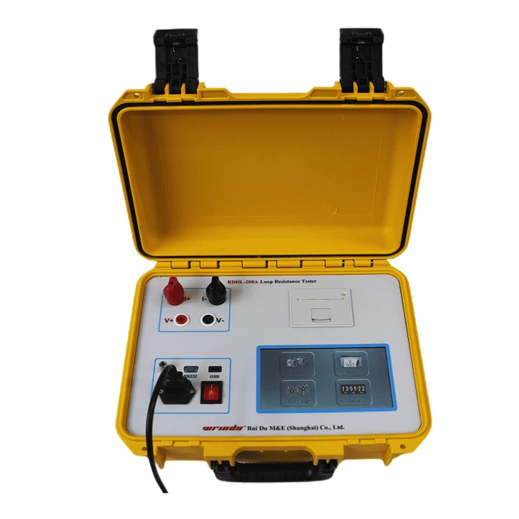
Image disclaimer: For identification and illustration only. It may show a product by another manufacturer and may not depict the exact item described; it is not a statement of any product’s quality, approval or performance. Third-party image and trademark rights belong to their owners. See full notice.
What Is It?
A Loop Resistance Meter (also known as a low-resistance ohmmeter or micro-ohmmeter) is a precision test instrument designed to measure very low resistances in AGL series circuits. It is specifically used to:
- Measure total loop resistance of the series circuit from the CCR output to the far end and back.
- Detect high-resistance connections at splices, terminal blocks, or isolating transformer connections.
- Verify circuit continuity and identify open circuits or broken conductors.
- Calculate voltage drop across the series loop for proper CCR sizing and operation.
- Trend resistance changes over time to detect gradual degradation due to corrosion or loose connections.
Unlike standard multimeters, loop resistance meters use a high test current (typically 1A to 10A) to overcome contact resistance effects and provide accurate measurements in the milliohm range. They are essential tools for commissioning, maintenance, and troubleshooting of AGL series circuits.
Purpose & Function
The loop resistance meter exists because a standard multimeter can't reliably detect the kind of subtle degradation that actually threatens an AGL series circuit — a slightly corroded splice or a loosening terminal connection that adds only a fraction of an ohm of resistance, but which will keep getting worse until it eventually causes a voltage drop severe enough to affect fixture brightness or trip the CCR. Using a higher test current lets this instrument see past contact-resistance noise and measure that small but meaningful change accurately.
Because it can trend resistance over time, its real value lies in catching a developing fault before it becomes an actual outage — a rising loop resistance reading during routine maintenance is a warning that a connection is degrading, giving technicians the chance to repair it proactively rather than waiting for a circuit to fail during live operations.
Where Is It Used?
Loop resistance meters are used across all phases of AGL circuit management:
- Installation Commissioning: Measuring loop resistance after cable installation to verify that connections are correct and within specification.
- Preventive Maintenance: Periodic measurement of loop resistance to detect increasing resistance due to corrosion, loose connections, or cable degradation.
- Fault Diagnosis: Locating high-resistance points in the loop that cause voltage drops, light intensity variations, or CCR instability.
- After Splice Repairs: Verifying that repairs have restored the loop to acceptable resistance values.
- Transformer Testing: Measuring the contribution of isolating transformers to the total loop resistance.
Testing is typically performed at the CCR output terminals with the circuit de-energized and all fixtures isolated (or with transformers in circuit, depending on the measurement objective).
Storage & Handling
The meter's four-terminal (Kelvin) leads are handled carefully and stored uncoiled or loosely coiled, since the accuracy of a milliohm-range measurement depends on clean, undamaged lead connections that a tightly wound or kinked lead can compromise over time. Test clips and probes are inspected for wear or corrosion before each use, given that even a small increase in contact resistance at the probe tip can be mistaken for a fault in the circuit being tested. The instrument is stored in its case within its rated temperature range, with batteries or the internal test-current source maintained per the manufacturer's guidance so the meter is ready to deliver its rated test current when next used. Because this instrument is often used to trend resistance values over months or years, it's kept on a strict calibration schedule so a reading taken today can be meaningfully compared against one taken at the last inspection.
How Does It Work?
A loop resistance meter operates on the four-wire (Kelvin) measurement principle to eliminate lead and contact resistance errors. The instrument:
- Applies a known DC test current (typically 1A to 10A) through the series loop using two "current" leads.
- Measures the voltage drop across the loop using two separate "potential" leads connected at the same points.
- Calculates resistance using Ohm's Law (R = V/I) with high accuracy down to micro-ohm levels.
- Displays resistance in milliohms (mΩ) or micro-ohms (µΩ) on a digital screen.
The four-wire method ensures that lead resistance and contact resistance do not affect the measurement, providing true loop resistance. Modern instruments include automatic ranging, data logging, and temperature compensation features. Some models can measure inductive components to evaluate transformer contributions.
System Architecture & Control Logic
The instrument's internal architecture exists mainly to keep the current-carrying and voltage-sensing paths electrically separate, since that separation is what the four-wire (Kelvin) method depends on. A constant-current source drives a known test current through the outer pair of leads (C1/C2) and into the loop under test, while a pair of dedicated potential leads (P1/P2), connected inside the current leads at the same physical points, feed a high-input-impedance differential amplifier that sees only the voltage drop across the loop itself — not the drop across the current leads' own resistance or their contact points. The MCU digitises this differential voltage, calculates R = V/I, and applies a temperature-compensation factor referenced to a standard conductor temperature (commonly 20°C) so results from different ambient conditions can be compared directly. On instruments that also report an inductive (reactive) component, the MCU drives the test current at more than one frequency and compares the phase and magnitude of the response to separate the loop's resistive and inductive contributions — relevant on AGL series circuits where an isolating transformer adds measurable inductance to what would otherwise be a pure resistance reading.
Why Four Wires: Separating Current from Sensing
Physical Construction
A loop resistance meter is built as a rugged hand-held instrument in an impact-resistant polymer case, with internal circuitry using a four-wire (Kelvin) measurement technique to eliminate lead and contact resistance from the reading, essential given the very low resistances the instrument is designed to measure. The test current source, typically a regulated constant-current circuit capable of delivering several amps, is housed alongside precision measurement electronics isolated from the current-carrying path to maintain accuracy across the instrument's wide auto-ranging span. Heavy-gauge test leads with Kelvin clip or probe terminations carry the current and sense connections separately to the circuit under test, and the front panel houses a backlit digital display along with controls for test current selection and data logging functions. A rechargeable battery pack powers the unit, and the case is built with a carrying strap, protective boot, or holster for use in the field around airfield cable pits and connector housings, with connection terminals arranged to resist dust and moisture ingress during outdoor testing.
Technical Parameters
| Parameter | Typical Value |
|---|---|
| Test Current | Selectable, typically 1 A to 10 A on the low-resistance ranges. High test current applies only at the milliohm end — measuring a multi-ohm series loop at 10 A would need a compliance voltage far beyond what a handheld instrument provides |
| Resistance Range | Micro-ohms to a few ohms at high test current; higher ranges (to hundreds or thousands of ohms) are measured at correspondingly lower current. Check the instrument’s current-versus-range table rather than assuming the headline current applies across the full span |
| Typical AGL Loop Values | A series lighting loop commonly falls between a fraction of an ohm and a few tens of ohms depending on cable length, conductor size and the number of isolating transformers — the useful measurement is the deviation from the commissioning baseline, not the absolute number |
| Accuracy | ±0.25% of reading ± 2 counts |
| Resolution | 0.1 µΩ (at lowest range) |
| Measurement Method | Four-wire (Kelvin) connection |
| Maximum Open Circuit Voltage | Low (commonly under about 10 V DC) — which is exactly why the instrument cannot drive its maximum test current into a high-resistance loop, and why the circuit must be isolated from the CCR and fully discharged before connection |
| Display | LCD with backlight, 4.5-digit |
| Data Storage | 1000+ test records with time/date |
| Interface | USB, Bluetooth, or RS-232 |
| Temperature Compensation | Automatic with an optional probe, referenced to 20°C — worth using, since copper resistance shifts roughly 0.4% per °C and an uncorrected summer-versus-winter comparison can look like a developing fault |
| Why Loop Resistance Matters | Loop resistance sets the voltage the regulator must produce to drive 6.6 A. As resistance rises, so does the required output; once it exceeds the CCR’s compliance voltage the regulator can no longer hold current and will alarm or shut down, so trending loop resistance is an early warning of splice and connector degradation |
| Power Supply | Rechargeable Li-ion battery or AC adapter |
| Safety Rating | CAT III 300V |
| Operating Temperature | -10°C to +50°C |
| Standards Compliance | IEC 61010-1, ASTM B539, IEEE 118 |
Applicable Standards
IEC 61010-1
Safety requirements for electrical test and measurement equipment
ASTM B539
Standard test method for measuring contact resistance of electrical connections
IEEE 118
Standard test code for resistance measurements
FAA AC 150/5340-26
Maintenance of Airport Visual Aid Facilities — series circuit and loop resistance testing guidance
Note on figures: the values on this page are typical reference figures drawn from the standards listed above and from manufacturers’ published data. Requirements differ between ICAO, FAA and national regimes, and between aerodrome code numbers, approach categories and equipment types. Always design, install, commission and maintain to the project specification, the manufacturer’s manual and the standard in force at the aerodrome.
Setup Requirements
Circuit De-Energisation & Isolation
Pre-UseConfirm the series circuit is isolated and de-energised before connecting the test leads.
Four-Wire Lead Connection
Pre-UseConnect the Kelvin leads with clean, undamaged probe tips to avoid contact-resistance error in the reading.
Zero/Null Calibration
Pre-UsePerform the zero/null function with the leads shorted before taking any circuit readings.
Calibration Currency Check
Pre-UseConfirm the instrument's calibration certificate is current before relying on the readings.
Known-Resistance Reference Check
Pre-UseVerify the meter against a known reference resistor before the first measurement of the session.
Testing & Commissioning
Visual & Physical Inspection
Receipt InspectionCheck the instrument on receipt for case damage and confirm the four-terminal (Kelvin) lead set is complete and undamaged.
Calibration Verification Against Reference Standard
Calibration VerificationCompare readings against a traceable low-resistance standard and confirm results fall within the manufacturer's accuracy specification across the milliohm range.
Zero / Null Function Check
Calibration VerificationVerify the zero/null function correctly cancels lead and contact resistance before a measurement is taken.
Four-Wire Lead Continuity Check
Functional AcceptanceConfirm each current-carrying and voltage-sensing lead pair is continuous and undamaged, since the four-wire method's accuracy depends on clean lead connections.
Known-Resistance Reference Measurement
Functional AcceptanceMeasure a known low-resistance reference component and confirm the reading matches its certified value within tolerance.
Documentation & Certification Sign-off
Final AcceptanceRecord calibration results and next due date on the instrument's calibration certificate before it is released for field use.
Inspection & Maintenance
Lead & Contact Inspection
Before each useCheck test leads and clips for damage or corrosion, which adds resistance error to readings.
Calibration Check
AnnualVerify readings against a certified reference resistor and recalibrate if drift exceeds tolerance.
Zero / Null Check
Before each useNull out lead resistance before taking measurements to avoid thermal EMF and contact resistance errors.
Common Field Issues
Lead and Contact Resistance Errors
Using two-wire (instead of four-wire) connections or poor test lead contacts can introduce significant errors. Always use the Kelvin (four-wire) method and ensure clean, tight connections at the test points.
Thermal EMF Effects
Thermoelectric voltages generated at dissimilar metal junctions can affect low-resistance measurements. Using AC test current or allowing thermal equilibrium before measurement can mitigate this.
Inductive Effects from Transformers
The presence of isolating transformers in the loop can cause inductive reactance that affects resistance readings. Using DC test current with appropriate settling time or using specialized instruments with inductive compensation can provide accurate results.
Troubleshooting Guide
Loop Resistance Reading Higher Than Expected
Readings Drift or Are Inconsistent Between Repeated Tests
Reading Appears Abnormally High on a Circuit with Isolating Transformers
Failure Modes & Root Causes
Calibration Drift
Test Lead or Probe Contact Degradation
Battery / Test Current Source Degradation
Display or Data-Logging Fault
Housing Seal Failure Allowing Moisture Ingress
Safety & Operational Notes
Circuit De-Energisation Before Testing
Electrical SafetyConfirm the loop under test is de-energised and isolated from its supply before connecting the meter, to protect both the instrument and the operator.
Calibration Currency Verification
OperationalCheck the meter's calibration due date before use and do not rely on results from an instrument that is out of calibration for pass/fail compliance decisions.
Weatherproofing of Field Connections
OperationalProtect test leads and probe connections from rain and standing water during field use, since moisture at the test point can produce a false low-resistance reading.
PPE / Insulated Test Leads
Personnel SafetyUse insulated test leads and appropriate PPE when connecting to field circuits, and treat every loop as potentially energised until isolation has been confirmed.
Battery Safety During Field Use
OperationalCheck battery condition before extended field testing and carry spares; a low battery can produce an inaccurate reading before the instrument indicates a fault.
Engineering & Expert Notes
Always Use Four-Wire Kelvin Connections, Never Two-Wire
MethodologyTwo-wire measurement includes the test lead and contact resistance in the result, which can dwarf the actual milliohm-range loop resistance being measured. Confirm four-wire Kelvin connections are used and that all four contact points are clean and tight before trusting a reading.
Let the Circuit Reach Thermal Equilibrium Before Testing
MethodologyThermoelectric voltages from dissimilar metal junctions in the loop can skew low-resistance readings if testing happens immediately after the circuit has been under load or exposed to rapid temperature change; allow settling time or use an instrument with thermal EMF compensation.
Isolating Transformers in the Loop Can Distort DC Readings if Not Accounted For
InstrumentationThe inductive reactance from transformers in a series loop can introduce measurement error with a standard DC test unless the instrument allows sufficient settling time or has inductive compensation; confirm the meter and method are appropriate for loops containing isolating transformers before trusting the result.
A Slowly Rising Baseline Is More Actionable Than a Single High Reading
TrendingLoop resistance typically climbs gradually as connections corrode or loosen, well before it causes an obvious fault; trend measurements over successive maintenance visits to catch degradation early rather than waiting for a reading that clearly exceeds a threshold.
Use Sectional Measurements to Localise a High-Resistance Connection
Fault IsolationA single end-to-end loop reading tells you something is wrong but not where; taking resistance measurements at intermediate splice points or terminal blocks narrows down the specific connection responsible far faster than working from the whole-loop number alone.
Record Test Current and Ambient Temperature With Every Measurement
DocumentationA milliohm reading without its test current and ambient temperature noted is hard to compare reliably against a future measurement taken under different conditions; log the full test parameters as standard practice, not just the resistance value.
Frequently Asked Questions
Short answers about the Loop Resistance Meter: what it is, how it works, typical specifications, standards, maintenance and common faults.
Q1What is a Loop Resistance Meter?
A Loop Resistance Meter (also known as a low-resistance ohmmeter or micro-ohmmeter) is a precision test instrument designed to measure very low resistances in AGL series circuits. It is specifically used to: Measure total loop resistance of the series circuit from the CCR output to the far end and back. Detect high-resistance connections at splices, terminal blocks, or isolating transformer connections. Verify circuit continuity and identify open circuits or broken conductors. Calculate voltage drop across the series loop for proper CCR sizing and operation.
Q2What is the purpose of a Loop Resistance Meter?
The loop resistance meter exists because a standard multimeter can't reliably detect the kind of subtle degradation that actually threatens an AGL series circuit — a slightly corroded splice or a loosening terminal connection that adds only a fraction of an ohm of resistance, but which will keep getting worse until it eventually causes a voltage drop severe enough to affect fixture brightness or trip the CCR. Using a higher test current lets this instrument see past contact-resistance noise and measure that small but meaningful change accurately.
Q3Where is a Loop Resistance Meter used?
Loop resistance meters are used across all phases of AGL circuit management: Installation Commissioning: Measuring loop resistance after cable installation to verify that connections are correct and within specification. Preventive Maintenance: Periodic measurement of loop resistance to detect increasing resistance due to corrosion, loose connections, or cable degradation. Fault Diagnosis: Locating high-resistance points in the loop that cause voltage drops, light intensity variations, or CCR instability. After Splice Repairs: Verifying that repairs have restored the loop to acceptable resistance values.
Q4How does a Loop Resistance Meter work?
A loop resistance meter operates on the four-wire (Kelvin) measurement principle to eliminate lead and contact resistance errors. The instrument: Applies a known DC test current (typically 1A to 10A) through the series loop using two "current" leads. Measures the voltage drop across the loop using two separate "potential" leads connected at the same points. Calculates resistance using Ohm's Law (R = V/I) with high accuracy down to micro-ohm levels. Displays resistance in milliohms (mΩ) or micro-ohms (µΩ) on a digital screen.
Q5How should a Loop Resistance Meter be stored and handled?
The meter's four-terminal (Kelvin) leads are handled carefully and stored uncoiled or loosely coiled, since the accuracy of a milliohm-range measurement depends on clean, undamaged lead connections that a tightly wound or kinked lead can compromise over time. Test clips and probes are inspected for wear or corrosion before each use, given that even a small increase in contact resistance at the probe tip can be mistaken for a fault in the circuit being tested.
Q6What are the typical technical parameters of a Loop Resistance Meter?
Typical values are — Test Current: Selectable, typically 1 A to 10 A on the low-resistance ranges. High test current applies only at the milliohm end — measuring a multi-ohm series loop at 10 A would need a compliance voltage far beyond what a handheld instrument provides; Resistance Range: Micro-ohms to a few ohms at high test current; higher ranges (to hundreds or thousands of ohms) are measured at correspondingly lower current. Check the instrument’s current-versus-range table rather than assuming the headline current applies across the full span.
Q7Which standards apply to a Loop Resistance Meter?
The main references are IEC 61010-1 — Safety requirements for electrical test and measurement equipment; ASTM B539 — Standard test method for measuring contact resistance of electrical connections; IEEE 118 — Standard test code for resistance measurements; FAA AC 150/5340-26 — Maintenance of Airport Visual Aid Facilities — series circuit and loop resistance testing guidance. Always verify the current edition and your aerodrome's approved requirements.
Q8How often should a Loop Resistance Meter be inspected and maintained?
Typical maintenance tasks and intervals are: Lead & Contact Inspection (before each use); Calibration Check (annual); Zero / Null Check (before each use). Your airport's approved maintenance programme takes precedence.
Q9How do I troubleshoot common Loop Resistance Meter faults?
Common symptoms covered are: Loop Resistance Reading Higher Than Expected; Readings Drift or Are Inconsistent Between Repeated Tests; Reading Appears Abnormally High on a Circuit with Isolating Transformers. For example, for "Loop Resistance Reading Higher Than Expected": Likely Cause: A two-wire connection was used instead of the four-wire (Kelvin) method, or test lead contacts are loose or corroded, adding extra resistance to the reading. Diagnostic Steps: Confirm the meter is connected using the four-wire Kelvin method; inspect test lead clamps and contact points for corrosion or looseness. Corrective Action: Reconnect using the correct four-wire method with clean, tight contacts, and repeat the measurement.
Related Components
Go Beyond the Component. Understand the Complete AGL System.
You have explored the component. Now understand how it works within the complete Airfield Ground Lighting system.
Learn AGL from fundamentals to design, installation, testing, photometry, commissioning, maintenance and troubleshooting through structured technical training at Precision AGL Academy.
Build practical knowledge. Understand the circuit. Read the standards. Troubleshoot with confidence.
Your next step in AGL starts here.
Need expert guidance on loop resistance meter selection or interpreting loop resistance measurements?
Precision AGL Academy provides advice on tester selection, test procedures, and analysis of loop resistance data for AGL systems.
Follow the Academy
Important Notice, Disclaimer & Limitation of Liability
Please read before relying on any content on this page.
- Purpose and intended users. This page on Loop Resistance Meter is an independent educational and informational reference for competent, suitably trained and authorised airfield ground lighting (AGL) and aerodrome electrical personnel. It is not professional engineering, legal or regulatory advice, and using it does not create any professional or client relationship.
- Safety. Work on series circuits, constant current regulators (CCRs), isolating transformers, cables, connectors and lighting equipment can be fatal. Always apply the aerodrome’s permit-to-work and isolation/LOTO procedures, prove dead, use correctly rated instruments and PPE, and follow the manufacturer’s instructions. Nothing here authorises work on live equipment or the bypassing of any safety device or interlock.
- Aviation operations. Nothing here authorises installation, modification, energisation, adjustment, return to service, a change of operating category (CAT I/II/III), a NOTAM or any aerodrome certification or approval decision. These rest with the aerodrome operator, the air navigation service provider and the competent regulator.
- Specifications, ratings and typical values. Descriptions, parameters, ratings, dimensions, photometric values, wattages, service lives, maintenance tasks and intervals, failure modes, certifications (for example CE, FCC, UL or IEC marks) and part or type designations are general, typical and indicative. They may not match any particular product, make, model or version, and they are not a datasheet, design, specification, selection, sizing, procurement or acceptance criterion. The manufacturer’s current documents, the approved design and the project specification prevail.
- Standards and regulations. References to ICAO, FAA, IEC, IEEE, ISO, BIS, DGCA and other standards are paraphrased summaries for orientation only. They may be incomplete or out of date, and standards are revised from time to time. Consult the current official editions. Following this content does not guarantee compliance with any law, standard or regulatory approval, and the regulator’s requirements always prevail.
- No warranty. Content is provided “as is” and “as available”, without warranty of any kind, express or implied, including accuracy, completeness, currency or fitness for a particular purpose. Real installations differ in design, equipment make and model, age and condition.
- Limitation of liability. To the fullest extent permitted by applicable law, Precision AGL Academy, Precision AGL Solutions and their owners, authors and contributors are not liable for any injury, death, loss, damage, downtime, penalty or regulatory consequence, whether direct or indirect, arising from the use of, reliance on, or inability to use this content. Nothing in this notice excludes or limits any liability that cannot lawfully be excluded or limited.
- Independence, brands and no endorsement. This is an independent publication. It is not affiliated with, sponsored by or endorsed by ICAO, the FAA, the IEC, DGCA, AAI, any airport, regulator, supplier or equipment manufacturer. Third-party names, product designations, standard designations and trademarks (including Megger®, Siemens, Eaton, Crouse-Hinds, ADB SAFEGATE, Fluke, ABB and Honeywell) belong to their respective owners and are used only for identification and description. Mention of a brand, product or supplier is not a recommendation, and we do not sell, supply or quote for any component described.
- Images and third-party content. Images and illustrations are shown to help identify the type of component. They may show products of various manufacturers, may not depict the exact item described, and are not a statement about any product’s quality, approval or performance. Copyright and trademarks in third-party images, logos and photographs belong to their respective owners and are not claimed as ours. If you are a rights holder and want an image removed, replaced or credited, email precisionaglsolutions@gmail.com with the page address and we will act promptly.
- Training and services. Mentions of training, courses, consultation, advice, selection, installation, calibration or other support, including the “Learn…Certify” pathway, describe learning stages and are not an offer, quotation, tender or promise of any result. Contacting us or our replying creates no engagement or duty of care; an engagement exists only under a written agreement. We are not a regulator or certification body, and completing any course or reading this content is not a certification, accreditation or authorisation to work on any aerodrome.
- Copyright, privacy and corrections. © 2026 Precision AGL Academy. All rights reserved. Text, structure, compilations and diagrams may be viewed for personal reference and internal training only; any other copying, republication or commercial use needs our written permission. If you email, telephone or message us, we use your details only to respond and handle your matter, in line with applicable Indian law including the Digital Personal Data Protection Act, 2023; please do not send confidential or security-sensitive information. To display this page your browser requests fonts, icons and images from third-party servers, which receive your IP address and browser details under their own policies. Content is reviewed periodically with no obligation to update. To report an error, safety concern or rights issue, write to precisionaglsolutions@gmail.com.