Ground‑Based Augmentation System (GBAS)
A satellite‑based navigation system that provides differential corrections and integrity monitoring for Global Positioning System (GPS) signals, enabling precision approaches (CAT I, II, III) with lateral and vertical guidance. GBAS enhances GPS accuracy, integrity, continuity, and availability, making it a vital component of modern air navigation infrastructure.
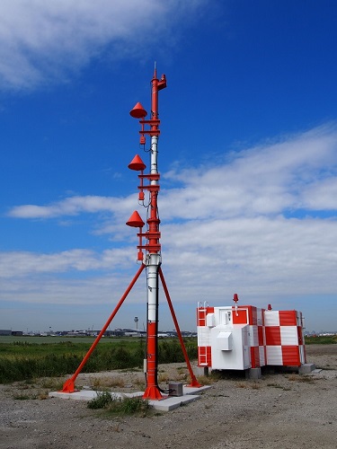
Image disclaimer: For identification and illustration only. It may show a product by another manufacturer and may not depict the exact item described; it is not a statement of any product’s quality, approval or performance. Third-party image and trademark rights belong to their owners. See full notice.
What Is It?
The Ground‑Based Augmentation System (GBAS) is a ground‑based system that augments the Global Positioning System (GPS) to provide enhanced navigation performance for aircraft. A GBAS installation typically consists of:
- Reference Receivers: A network of GPS reference receivers located at surveyed positions around the airport. These receivers measure GPS signal errors (ionospheric, tropospheric, satellite clock, and ephemeris errors).
- Central Processing Station: A ground computer that processes the reference receiver data to generate differential corrections and integrity parameters.
- VHF Data Broadcast (VDB): A VHF transmitter that broadcasts the correction and integrity data to aircraft within the coverage area (typically about 20 nautical miles).
Aircraft equipped with a GBAS receiver use the broadcast data to compute a highly accurate, integrity‑monitored position, enabling precision approaches (CAT I, II, III) with lateral and vertical guidance. GBAS is increasingly positioned as a longer-term successor to the Instrument Landing System (ILS), with a growing number of installations at major airports worldwide, offering multiple approach paths and greater flexibility than a fixed ILS beam can provide.
Purpose & Function
GBAS exists to deliver the same category of precision approach guidance as ILS, lateral and vertical, down to CAT III minima, from a single ground installation that can support every runway and multiple approach paths at an airport rather than requiring a dedicated localizer and glide slope pair for each runway end. Its purpose is achieved by applying the same correction-and-integrity principle as wide-area SBAS, but concentrated locally around one airport using its own reference receivers and VHF broadcast, which gives it tighter local accuracy and lower latency than a wide-area system could provide for approach-critical guidance. That local scope is also what lets GBAS support curved or offset approach paths that a fixed ILS beam geometry cannot offer, giving airports more flexibility in how aircraft are guided to each runway.
Where Is It Used?
GBAS is used for a wide range of applications across all phases of flight:
- Precision Approaches: GBAS supports CAT I, II, and III precision approaches, providing lateral and vertical guidance to the runway. It allows for multiple approach paths (e.g., curved approaches) and can serve all runway ends from a single installation.
- Terminal Area Navigation: GBAS provides accurate positioning for departure and arrival procedures, including RNAV/RNP operations.
- En‑route Navigation: GBAS corrections can improve en‑route GPS accuracy, though coverage is typically limited to the airport vicinity.
- Surface Navigation: GBAS can provide accurate positioning for airport surface movement guidance, including A‑SMGCS applications.
- Remote and Offshore Operations: GBAS is particularly valuable in areas where ILS installations are impractical or expensive, such as offshore heliports or remote airstrips.
Installation & Location
Reference receivers are distributed around the airfield on surveyed monuments, spaced apart and sited with a clear view of the sky to minimise multipath and ensure the array as a whole sees consistent satellite geometry; their antennas are mounted on short masts or building rooftops away from large reflective surfaces. The central processing station and VHF data broadcast (VDB) transmitter are housed together in an equipment building, with the VDB antenna mounted on a mast sited to give unobstructed line of sight over the runway and approach/departure paths it serves. Cabling from each reference receiver back to the processing station is run in duct, and the facility is connected to airport standby power in the same way as other critical navigation aids, given its role in supporting precision approaches.
How Does It Work?
The GBAS system operates through a multi‑step process:
- Reference Measurements: The reference receivers track all visible GPS satellites and measure pseudorange and carrier‑phase observables. These measurements are compared with the known positions of the receivers to calculate ranging errors.
- Differential Corrections: The central processing station computes differential corrections for each satellite in view. These corrections include ionospheric delay, tropospheric delay, satellite clock errors, and ephemeris errors.
- Integrity Monitoring: The system continuously monitors the health of the GPS constellation and the ground equipment. It generates integrity parameters — a ground accuracy designator (σ_pr_gnd) and per-receiver B-values derived by cross-checking the redundant reference receivers against each other — that allow the aircraft receiver to assess the reliability of the corrections and detect a faulty measurement before it propagates into the position solution.
- Data Broadcast: The VDB transmitter broadcasts the corrections, integrity data, and approach path information (waypoints, glide path angle, etc.) on a VHF frequency (108.025–117.950 MHz, in 25 kHz channel steps, paired with the approach procedure).
- Aircraft Processing: The aircraft's GBAS receiver uses the broadcast data to correct its GPS measurements, compute a precise position, and generate lateral and vertical deviation signals for the cockpit display (similar to ILS).
System Architecture & Control Logic
A GBAS ground facility's control logic centres on redundant reference receivers feeding a central integrity processor. Multiple GNSS reference receivers, sited around the airfield, each independently compute pseudorange corrections; the processor cross-checks these against one another to detect a faulty receiver or a satellite anomaly before it can propagate to an aircraft. Corrections, approach path definitions and integrity parameters are packaged and broadcast continuously over the VHF Data Broadcast (VDB) link at the required message rate, so aircraft are never operating on stale data. If the processor cannot certify the correction data within the required integrity bounds, it withholds or flags the broadcast rather than transmit an unverified correction, with status reported to the ATC and maintenance monitoring system.
Reference Receivers → Integrity Processor → VDB Broadcast → Aircraft GBAS Receiver
Signal & Data Flow
Physical Construction
The GBAS ground facility comprises a small number of precisely surveyed GPS reference receiver antennas mounted on short masts around the airfield, each connected via shielded, lightning-protected cabling back to a central processing cabinet housing the redundant reference receivers, integrity-monitoring processors, and VHF Data Broadcast (VDB) transmitter. The VDB transmit antenna is mounted at an elevated, unobstructed location to achieve its rated coverage radius, with the equipment cabinet built as a weatherproof, temperature-controlled enclosure similar to other NAVAID ground stations. Internally, the reference receivers and VDB transmitter chains are duplicated for hot-standby redundancy, with automatic switchover logic and continuous integrity monitoring built into the processing electronics to meet the stringent CAT I/II/III integrity and continuity requirements. Surge protection and isolation are fitted at every antenna feed and external interface given the facility's exposure to lightning and RF interference, and the cabinet's power section connects to mains, UPS, and generator backup for uninterrupted operation.
Technical Parameters
| Parameter | Typical Value |
|---|---|
| Frequency (GPS) | L1 (1575.42 MHz), L2 (1227.60 MHz), L5 (1176.45 MHz) |
| VDB Frequency Range | 108.025 MHz – 117.950 MHz, 25 kHz channel spacing (paired with approach procedure) |
| VDB Modulation | D8PSK (Data‑8 Phase Shift Keying) |
| VDB Data Rate | 31.5 kbps (10.5 kbaud × 3 bits/symbol, D8PSK) |
| VDB Coverage | Typically up to 20 NM (37 km) radius |
| Approach Accuracy | 95% position error: Lateral ≤ 16 m, Vertical ≤ 4 m (CAT I / GAST-C, per ICAO Annex 10) |
| Integrity | Integrity risk < 10⁻⁷ per approach (CAT I) |
| Continuity | > 99.99% |
| Availability | > 99.9% (CAT I) |
| CAT Capability | CAT I, II, III (depending on installation and certification) |
| Standby System | Dual redundant (hot standby) for critical components |
| Power Supply | Mains with UPS and generator backup |
| Protection Class | IP65 / IP67 (weatherproof for outdoor equipment) |
Electrical Requirements
| Requirement | Typical Value |
|---|---|
| Primary Supply | Mains AC feed to the ground facility, backed by UPS and standby generator |
| Changeover | Automatic transfer between mains, UPS, and generator with no interruption to VDB transmission or reference receiver operation |
| Cabling | Dedicated feeder from the airfield distribution point to the ground facility, sized to the equipment's rated load |
| Circuit Protection | Dedicated circuit breaker/isolator at the facility distribution board |
| Surge Protection | SPDs fitted at the power, antenna, and reference-receiver cable entries |
| Insulation Resistance | ≥ 50 MΩ (megger test, cable-to-ground, at commissioning) |
| Earthing/Grounding | Facility, mast, and reference receiver antennas bonded to the airfield earth grid |
| Fault Protection | Continuous self-monitoring with alarm reporting to the remote status panel on power or subsystem fault |
Applicable Standards
ICAO Annex 10
GBAS frequency, modulation, and performance requirements
FAA Order 6884.1
Siting Criteria for Ground Based Augmentation System (GBAS) Ground Facility
EUROCAE ED-114
GBAS ground station performance and monitoring standards
RTCA DO-253
Minimum Operational Performance Standards (MOPS) for GBAS airborne receiver equipment
Installation Requirements
Reference Receiver Monument Survey
SiteEstablish surveyed monument positions distributed around the airfield, spaced apart with a clear view of the sky to minimise multipath and ensure consistent satellite geometry across the array.
Reference Antenna Mast/Rooftop Mounting
CivilMount each reference antenna on a short mast or building rooftop, away from large reflective surfaces.
VDB Antenna Mast Siting
CivilSite the VDB antenna mast for unobstructed line of sight over the runway and the approach/departure paths it serves.
Duct & Cable Route to Processing Station
ElectricalRun cabling from each reference receiver back to the central processing station in duct.
Standby Power Connection
ElectricalConnect the facility to airport standby power, matching the arrangement used for other critical navigation aids.
Equipment Building Fit-Out
MechanicalInstall the central processing station and VDB transmitter together within the equipment building.
Satellite Geometry/Multipath Check
DocumentationVerify the reference receiver array as a whole sees consistent satellite geometry before commissioning.
Pre-Energisation Sign-off
DocumentationRecord monument survey coordinates, mast positions, and cable routes as-built before the facility is closed up.
Testing & Commissioning
Reference Receiver Position Survey Verification
Pre-EnergisationConfirm each reference antenna's surveyed position meets the accuracy required for GBAS correction data before the receivers are brought into service.
VDB Frequency & Power Output Test
CommissioningVerify the VHF Data Broadcast transmits on its assigned frequency at the correct power and modulation (D8PSK) to achieve rated coverage.
Integrity Monitoring Function Test
CommissioningInject simulated fault conditions and confirm the integrity-monitoring processors detect and flag them within the required time to meet CAT I/II/III integrity requirements.
Redundancy Switchover Test
CommissioningSimulate a fault on the primary reference receiver or VDB transmitter chain and confirm automatic switchover to the hot-standby unit.
Data Broadcast Message Verification
CommissioningDecode the broadcast correction and approach path data with a test receiver to confirm message content matches the published procedure.
Approach Accuracy Flight Check
Final AcceptanceVerify lateral and vertical guidance accuracy against the certified tolerance using a calibrated flight-check aircraft before operational release.
Documentation & As-Built Sign-off
Final AcceptanceRecord survey data, VDB test results, integrity monitoring performance, and flight-check results in the commissioning dossier.
Inspection & Maintenance
GPS Signal Environment Survey
AnnualSurvey the site for new sources of GPS interference or jamming that could affect signal integrity.
VDB Coverage Check
AnnualVerify VHF data broadcast coverage across the approach area, checking for multipath-affected zones.
Reference Receiver Calibration Check
AnnualVerify reference receiver calibration against a known-position benchmark.
Integrity Monitoring Function Test
Semi-annualTest integrity monitoring functions to confirm faults would be correctly detected and flagged.
Common Field Issues
GPS Signal Interference and Jamming
GBAS is dependent on GPS signals, which are vulnerable to interference (intentional or unintentional) and ionospheric scintillation. Sites must be carefully surveyed for potential interference sources, and mitigation measures (e.g., antenna filtering, site shielding) are essential.
VDB Coverage and Multipath
The VHF data broadcast is line‑of‑sight and can be affected by terrain, buildings, and aircraft shadowing. Proper antenna placement and power selection are critical to ensure coverage over the entire approach path.
Reference Receiver Calibration
The reference receivers must be precisely surveyed and regularly calibrated to maintain system accuracy. Any shift in the reference receiver position can degrade the differential corrections.
Integrity Monitoring Failures
The integrity monitoring subsystem must reliably detect and alert on any satellite or ground system failures. False alarms can reduce system availability, while missed detections can compromise safety. Regular testing and validation are required.
Troubleshooting Guide
Loss of GPS Signal Tracking or Sudden Availability Drop
VDB Coverage Gaps on the Approach Path
Differential Corrections Appear Degraded
Integrity Monitor Triggers False Alarms or Fails to Alert
Failure Modes & Root Causes
GPS Interference or Ionospheric Scintillation
VDB Coverage Obstruction or Transmitter Fault
Reference Receiver Position Drift
Integrity Monitor Miscalibration
Safety & Operational Notes
RF Exposure Near the VDB Antenna
Personnel SafetyFollow the facility's RF safety procedure and any posted exclusion distance when working near the VHF Data Broadcast transmit antenna, and confirm the transmitter is placed in maintenance/standby mode before working at or above the antenna mast.
Equipment Cabinet Isolation
Electrical SafetyDe-energise and lock out the reference receiver or VDB transmitter chain before working inside the processing cabinet, and verify zero energy before disturbing internal connections.
Reference Receiver Antenna Survey Integrity
ComplianceDo not move, re-mount, or replace a reference receiver antenna without re-surveying its position; the system's integrity depends on each antenna's surveyed location being accurate to a high tolerance.
Lightning Exposure at Mast-Mounted Antennas
Electrical SafetyVerify surge protection is in place and intact at every antenna feed before working on cabling, given the facility's exposure to lightning, and avoid antenna or mast work during an active electrical storm.
NOTAM for Service Interruption
OperationalIssue a NOTAM before taking the GBAS facility out of service or below integrity tolerance for maintenance, since aircraft rely on it for precision approach guidance.
Verify Integrity Monitoring Before Return to Service
ComplianceConfirm the integrity processor correctly detects a faulty receiver or out-of-tolerance correction and withholds the broadcast before returning the facility to service after maintenance affecting the reference receivers or processor.
PPE & Grounding
Personnel SafetyUse appropriate PPE and confirm the facility, mast, and reference receiver antennas remain bonded to the airfield earth grid before closing out cabling work.
Restore to Compliant State
ComplianceDo not leave the facility broadcasting corrections outside CAT I/II/III integrity and continuity requirements after maintenance; verify monitored parameters before closing out the work and cancelling the associated NOTAM.
Engineering & Expert Notes
Multipath Faults Look Like Receiver Faults
DiagnosticsAn intermittent integrity flag that clears on receiver reset is frequently a multipath issue from a new reflective surface near the reference receivers, such as a parked vehicle or vehicle mast, rather than an actual receiver fault. Check the site line-of-sight environment before swapping hardware.
Reference Receiver Antenna Survey Drifts Over Time
PrecisionGround settlement or minor structural movement of a reference receiver antenna mount over years of service can introduce a small but real position error into the correction message. Periodic re-survey of antenna coordinates belongs in the maintenance cycle, not just at commissioning.
VDB Coverage Complaints Often Trace to Siting, Not Power
TroubleshootingA reported VHF data broadcast coverage gap along a particular approach is more often caused by terrain or structure shadowing at that specific bearing than by transmitter power. Check the site's coverage prediction against the reported bearing before adjusting transmit power.
Trend Integrity Alarms, Don't Just Clear Them
ProcessA GBAS integrity alarm that self-clears on the next cycle can still be an early indicator of a satellite geometry or ionospheric issue recurring at a predictable time of day. Log alarm timing and conditions rather than treating each clear as resolved.
Ionospheric Activity Drives Seasonal Alarm Patterns
EnvironmentIntegrity alarm rates for GBAS installations tend to rise during periods of high ionospheric disturbance. When troubleshooting a spike in alarms, check regional space-weather activity before assuming a local equipment fault.
Keep Redundant Receiver Data Independently Logged
DesignWhere multiple reference receivers feed a single processing path, log each receiver's raw data independently rather than only the combined output. This makes it possible to isolate which specific receiver degraded first when a fault eventually shows up in the combined correction.
Frequently Asked Questions
Short answers about the Ground-Based Augmentation System (GBAS): what it is, how it works, typical specifications, standards, maintenance and common faults.
Q1What is a Ground-Based Augmentation System (GBAS)?
The Ground‑Based Augmentation System (GBAS) is a ground‑based system that augments the Global Positioning System (GPS) to provide enhanced navigation performance for aircraft. A GBAS installation typically consists of: Reference Receivers: A network of GPS reference receivers located at surveyed positions around the airport. These receivers measure GPS signal errors (ionospheric, tropospheric, satellite clock, and ephemeris errors). Central Processing Station: A ground computer that processes the reference receiver data to generate differential corrections and integrity parameters.
Q2What is the purpose of a Ground-Based Augmentation System (GBAS)?
GBAS exists to deliver the same category of precision approach guidance as ILS, lateral and vertical, down to CAT III minima, from a single ground installation that can support every runway and multiple approach paths at an airport rather than requiring a dedicated localizer and glide slope pair for each runway end.
Q3Where is a Ground-Based Augmentation System (GBAS) used and installed?
GBAS is used for a wide range of applications across all phases of flight: Precision Approaches: GBAS supports CAT I, II, and III precision approaches, providing lateral and vertical guidance to the runway. It allows for multiple approach paths (e.g., curved approaches) and can serve all runway ends from a single installation. Terminal Area Navigation: GBAS provides accurate positioning for departure and arrival procedures, including RNAV/RNP operations. En‑route Navigation: GBAS corrections can improve en‑route GPS accuracy, though coverage is typically limited to the airport vicinity.
Q4How does a Ground-Based Augmentation System (GBAS) work?
The GBAS system operates through a multi‑step process: Reference Measurements: The reference receivers track all visible GPS satellites and measure pseudorange and carrier‑phase observables. These measurements are compared with the known positions of the receivers to calculate ranging errors. Differential Corrections: The central processing station computes differential corrections for each satellite in view. These corrections include ionospheric delay, tropospheric delay, satellite clock errors, and ephemeris errors. Integrity Monitoring: The system continuously monitors the health of the GPS constellation and the ground equipment.
Q5What are the typical technical parameters of a Ground-Based Augmentation System (GBAS)?
Typical values are — Frequency (GPS): L1 (1575.42 MHz), L2 (1227.60 MHz), L5 (1176.45 MHz); VDB Frequency Range: 108.025 MHz – 117.950 MHz, 25 kHz channel spacing (paired with approach procedure); VDB Modulation: D8PSK (Data‑8 Phase Shift Keying); VDB Data Rate: 31.5 kbps (10.5 kbaud × 3 bits/symbol, D8PSK); VDB Coverage: Typically up to 20 NM (37 km) radius; Approach Accuracy: 95% position error: Lateral ≤ 16 m, Vertical ≤ 4 m (CAT I / GAST-C, per ICAO Annex 10); Integrity: Integrity risk < 10⁻⁷ per approach (CAT I); Continuity: > 99.99%; Availability: > 99.9% (CAT I); CAT Capability: CAT I, II, III (depending on installation and certification).
Q6What are the electrical requirements for a Ground-Based Augmentation System (GBAS)?
Typical requirements are — Primary Supply: Mains AC feed to the ground facility, backed by UPS and standby generator; Changeover: Automatic transfer between mains, UPS, and generator with no interruption to VDB transmission or reference receiver operation; Cabling: Dedicated feeder from the airfield distribution point to the ground facility, sized to the equipment's rated load; Circuit Protection: Dedicated circuit breaker/isolator at the facility distribution board; Surge Protection: SPDs fitted at the power, antenna, and reference-receiver cable entries; Insulation Resistance: ≥ 50 MΩ (megger test, cable-to-ground, at commissioning).
Q7Which standards apply to a Ground-Based Augmentation System (GBAS)?
The main references are ICAO Annex 10 — GBAS frequency, modulation, and performance requirements; FAA Order 6884.1 — Siting Criteria for Ground Based Augmentation System (GBAS) Ground Facility; EUROCAE ED-114 — GBAS ground station performance and monitoring standards; RTCA DO-253 — Minimum Operational Performance Standards (MOPS) for GBAS airborne receiver equipment. Always verify the current edition and your aerodrome's approved requirements.
Q8How often should a Ground-Based Augmentation System (GBAS) be inspected and maintained?
Typical maintenance tasks and intervals are: GPS Signal Environment Survey (annual); VDB Coverage Check (annual); Reference Receiver Calibration Check (annual); Integrity Monitoring Function Test (semi-annual). Your airport's approved maintenance programme takes precedence.
Q9How do I troubleshoot common Ground-Based Augmentation System (GBAS) faults?
Common symptoms covered are: Loss of GPS Signal Tracking or Sudden Availability Drop; VDB Coverage Gaps on the Approach Path; Differential Corrections Appear Degraded; Integrity Monitor Triggers False Alarms or Fails to Alert. For example, for "Loss of GPS Signal Tracking or Sudden Availability Drop": Likely Cause: GPS interference or jamming (intentional or unintentional), or ionospheric scintillation affecting satellite signal reception at the reference receivers. Diagnostic Steps: Review the reference receiver logs for satellite dropouts and carrier-to-noise ratio trends; check for known interference sources or scintillation activity reports for the region; confirm all reference receivers are affected equally versus a single-unit fault. Corrective Action: Coordinate with spectrum management if interference is confirmed; if scintillation-related, this may be a transient condition — monitor and report per procedure rather than replacing hardware prematurely.
Related Components
Go Beyond the Component. Understand the Complete AGL System.
You have explored the component. Now understand how it works within the complete Airfield Ground Lighting system.
Learn AGL from fundamentals to design, installation, testing, photometry, commissioning, maintenance and troubleshooting through structured technical training at Precision AGL Academy.
Build practical knowledge. Understand the circuit. Read the standards. Troubleshoot with confidence.
Your next step in AGL starts here.
Need expert guidance on GBAS selection, installation, or troubleshooting?
Precision AGL Academy provides advice on site planning, signal optimization, and flight inspection preparation for GBAS systems.
Follow the Academy
Important Notice, Disclaimer & Limitation of Liability
Please read before relying on any content on this page.
- Purpose and intended users. This page on Ground‑Based Augmentation System (GBAS) is an independent educational and informational reference for competent, suitably trained and authorised airfield ground lighting (AGL) and aerodrome electrical personnel. It is not professional engineering, legal or regulatory advice, and using it does not create any professional or client relationship.
- Safety. Work on series circuits, constant current regulators (CCRs), isolating transformers, cables, connectors and lighting equipment can be fatal. Always apply the aerodrome’s permit-to-work and isolation/LOTO procedures, prove dead, use correctly rated instruments and PPE, and follow the manufacturer’s instructions. Nothing here authorises work on live equipment or the bypassing of any safety device or interlock.
- Aviation operations. Nothing here authorises installation, modification, energisation, adjustment, return to service, a change of operating category (CAT I/II/III), a NOTAM or any aerodrome certification or approval decision. These rest with the aerodrome operator, the air navigation service provider and the competent regulator.
- Specifications, ratings and typical values. Descriptions, parameters, ratings, dimensions, photometric values, wattages, service lives, maintenance tasks and intervals, failure modes, certifications (for example CE, FCC, UL or IEC marks) and part or type designations are general, typical and indicative. They may not match any particular product, make, model or version, and they are not a datasheet, design, specification, selection, sizing, procurement or acceptance criterion. The manufacturer’s current documents, the approved design and the project specification prevail.
- Standards and regulations. References to ICAO, FAA, IEC, IEEE, ISO, BIS, DGCA and other standards are paraphrased summaries for orientation only. They may be incomplete or out of date, and standards are revised from time to time. Consult the current official editions. Following this content does not guarantee compliance with any law, standard or regulatory approval, and the regulator’s requirements always prevail.
- No warranty. Content is provided “as is” and “as available”, without warranty of any kind, express or implied, including accuracy, completeness, currency or fitness for a particular purpose. Real installations differ in design, equipment make and model, age and condition.
- Limitation of liability. To the fullest extent permitted by applicable law, Precision AGL Academy, Precision AGL Solutions and their owners, authors and contributors are not liable for any injury, death, loss, damage, downtime, penalty or regulatory consequence, whether direct or indirect, arising from the use of, reliance on, or inability to use this content. Nothing in this notice excludes or limits any liability that cannot lawfully be excluded or limited.
- Independence, brands and no endorsement. This is an independent publication. It is not affiliated with, sponsored by or endorsed by ICAO, the FAA, the IEC, DGCA, AAI, any airport, regulator, supplier or equipment manufacturer. Third-party names, product designations, standard designations and trademarks (including Megger®, Siemens, Eaton, Crouse-Hinds, ADB SAFEGATE, Fluke, ABB and Honeywell) belong to their respective owners and are used only for identification and description. Mention of a brand, product or supplier is not a recommendation, and we do not sell, supply or quote for any component described.
- Images and third-party content. Images and illustrations are shown to help identify the type of component. They may show products of various manufacturers, may not depict the exact item described, and are not a statement about any product’s quality, approval or performance. Copyright and trademarks in third-party images, logos and photographs belong to their respective owners and are not claimed as ours. If you are a rights holder and want an image removed, replaced or credited, email precisionaglsolutions@gmail.com with the page address and we will act promptly.
- Training and services. Mentions of training, courses, consultation, advice, selection, installation, calibration or other support, including the “Learn…Certify” pathway, describe learning stages and are not an offer, quotation, tender or promise of any result. Contacting us or our replying creates no engagement or duty of care; an engagement exists only under a written agreement. We are not a regulator or certification body, and completing any course or reading this content is not a certification, accreditation or authorisation to work on any aerodrome.
- Copyright, privacy and corrections. © 2026 Precision AGL Academy. All rights reserved. Text, structure, compilations and diagrams may be viewed for personal reference and internal training only; any other copying, republication or commercial use needs our written permission. If you email, telephone or message us, we use your details only to respond and handle your matter, in line with applicable Indian law including the Digital Personal Data Protection Act, 2023; please do not send confidential or security-sensitive information. To display this page your browser requests fonts, icons and images from third-party servers, which receive your IP address and browser details under their own policies. Content is reviewed periodically with no obligation to update. To report an error, safety concern or rights issue, write to precisionaglsolutions@gmail.com.