Airfield Environmental Sensors
The network of visibility, wind, and weather sensors that feed real-time data to air traffic control, pilots, and ALCMS — enabling safe operations and informed intensity decisions for approach lighting and runway visual range reporting.
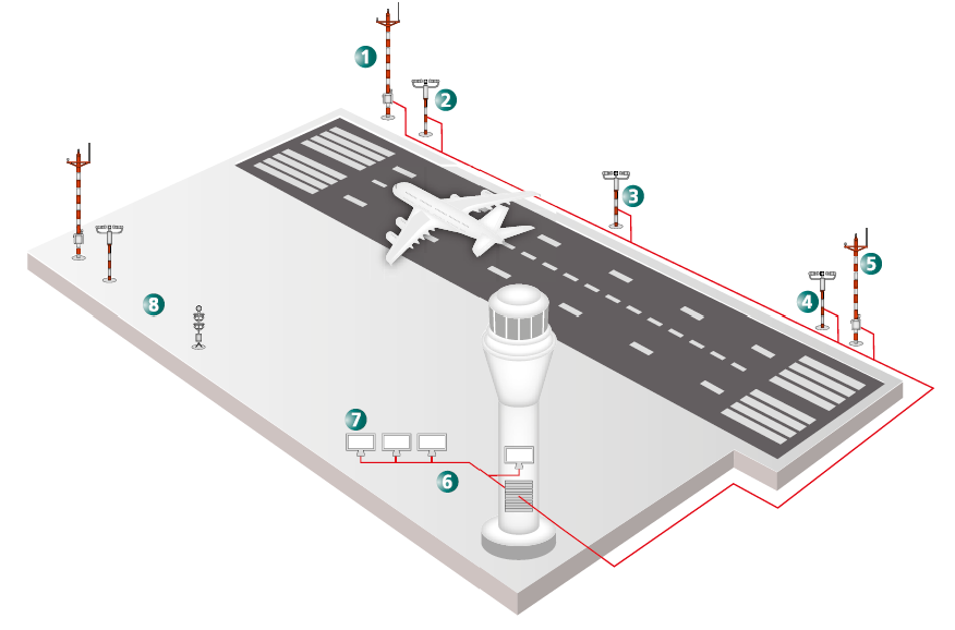
Image disclaimer: For identification and illustration only. It may show a product by another manufacturer and may not depict the exact item described; it is not a statement of any product’s quality, approval or performance. Third-party image and trademark rights belong to their owners. See full notice.
What Are They?
Airfield environmental sensors are the suite of instruments that measure meteorological conditions critical to aviation safety — visibility (RVR – Runway Visual Range), wind speed and direction, temperature, humidity, barometric pressure, and precipitation. These sensors are typically installed alongside runways, at thresholds, and at mid‑points, and they feed data to the control tower, MET office, and increasingly to the ALCMS for automated lighting intensity adjustments.
RVR (Runway Visual Range) is a derived value that combines visibility, background luminance, and runway light intensity to estimate the distance a pilot can see runway markings or lights. It is measured using forward-scatter or transmissometer sensors installed at the touchdown, mid, and stop‑end points of each runway.
Wind sensors (anemometers and wind vanes) provide real-time wind speed, gust, and direction, essential for takeoff and landing decisions. Wind data is also used to calculate crosswind and tailwind components.
Purpose & Function
The safety margins built into aviation operations depend on knowing the actual visibility and wind conditions at the runway right now, not an estimate from a tower window or a forecast from an hour ago. Environmental sensors exist to replace that kind of subjective or stale judgement with a continuous, instrumented measurement pilots, ATC, and airfield systems can rely on. RVR sensors give a specific, defensible distance figure for how far a pilot can actually expect to see runway lights or markings — the number that determines whether an approach or takeoff is permitted to proceed under a given category of operation. Wind sensors give the crosswind and tailwind components that decide which runway is safe to use and whether conditions remain within an aircraft's operating limits. Feeding this same data into the ALCMS closes a further gap: rather than running the runway lighting at a fixed default intensity, the system can match light output to the visibility that has actually been measured, so pilots see the intensity level appropriate to conditions rather than one set for the worst case or guessed by an operator.
Where Are They Used?
Environmental sensors are strategically placed across the airfield to capture representative conditions:
- RVR Sensors (Transmissometers / Forward Scatter): Installed at three positions along each runway — touchdown zone (typically 300m from threshold), mid-point, and stop end — to provide RVR values for the full runway.
- Wind Sensors: Typically mounted on masts near the runway thresholds (both ends) and at mid-field, to capture surface wind conditions.
- Automatic Weather Observing Systems (AWOS): Integrated sensor suites that include temperature, humidity, dew point, barometric pressure, and precipitation detection.
- Ceilometers: Measure cloud base height, important for approach minima.
- Present Weather Sensors: Detect precipitation type (rain, snow, drizzle) and intensity.
Data from these sensors is distributed to ATC, the aerodrome meteorological office, and, in modern systems, directly to the ALCMS for automated intensity step selection based on RVR thresholds.
Installation & Location
RVR transmissometers and forward-scatter sensors are mounted on short masts a set offset from the runway centreline at each of the touchdown, mid-point, and stop-end positions, sited so the sensor's optical path is clear of any obstruction and positioned to keep the equipment within the runway strip's obstacle-limitation surface. Wind masts are erected near each runway threshold and at mid-field, at a height and distance from the runway that avoids local turbulence from nearby structures or terrain skewing the reading, with the sensor itself mounted at the standard reference height above ground level used for the airfield's wind reporting. All sensor types are fed by cable — power and signal — run in duct or direct-buried conduit back to a local remote terminal unit or straight to the AWOS processing equipment, with the cable route planned to avoid the runway strip's graded and load-bearing areas. Because these sensors report values pilots and ATC act on directly, foundation and mast installation is carried out under a survey that fixes each sensor's exact position and height, since even a modest siting error can bias the readings the whole safety margin depends on.
How Do They Work?
Each sensor type uses a distinct measurement principle:
- Transmissometer: Measures the extinction of a light beam over a known baseline (typically 75m). The receiver measures the transmitted light, and the instrument calculates the Meteorological Optical Range (MOR). RVR is then derived using background luminance and runway light intensity.
- Forward Scatter Sensor: Measures the amount of light scattered by particles in a small sample volume. It is more compact than a transmissometer and is widely used as an alternative.
- Anemometer: Uses a three‑cup or ultrasonic design to measure wind speed, and a vane or sonic array for direction. Ultrasonic anemometers are increasingly preferred for their lack of moving parts.
- Temperature / Humidity Sensors: Typically platinum resistance thermometers (PRT) and capacitive humidity sensors housed in a radiation shield.
- Ceilometer: Uses a laser or infrared beam to detect cloud base height by measuring the time of flight of backscattered light.
All sensors are connected to a data acquisition system (often an AWOS) that processes, formats, and transmits data to displays and networked systems. Data is typically updated once per minute or faster.
System Architecture & Control Logic
Individual environmental sensors — transmissometers, forward-scatter sensors, anemometers, temperature/humidity probes, ceilometers — each measure a single physical quantity and have no interconnection with one another; the control architecture lives in the data acquisition and processing layer above them. Each sensor's analogue or digital output is polled by a local data acquisition unit, which timestamps and validates the reading (flagging out-of-range or stuck values) before forwarding it to the central AWOS processor. The AWOS processor combines readings from multiple sensor sites, applies the required algorithms — deriving RVR from MOR and background luminance, for instance — and pushes the resulting product to ATC and pilot-facing displays, typically refreshing at least once a minute; if a sensor drops out or its data fails validation, the processor flags that specific parameter as unavailable rather than silently substituting a stale or estimated value.
Sensor → Data Acquisition Unit → AWOS Processor → Derived Products → ATC / Pilot Displays
Data Acquisition Path
Physical Construction
Each sensor type within an environmental sensor suite follows construction appropriate to its measurement principle, but shares common design features: a weatherproof sensor head or optical assembly, typically aluminium or corrosion-resistant composite, rated to IP66/IP67, mounted on a rigid pole or mast at a height standardised for that measurement type. Optical sensors such as RVR and visibility instruments house their transmitter and receiver components in sealed enclosures with heated windows to prevent condensation or icing from obscuring the measurement path, while wind and temperature sensors use sealed bearing assemblies or radiation shields appropriate to their mechanism. All sensor heads connect via shielded, weather-rated cable to a common signal processing or data concentrator unit, often housed in a nearby equipment cabinet, which aggregates readings from the full sensor suite before forwarding them to the ALCMS or MET office over the site communication network. Mounting structures are corrosion-resistant steel or aluminium poles set in concrete foundations, positioned to keep each sensor clear of obstructions or turbulence sources that could bias its readings, and all outdoor enclosures and cabling are built to withstand continuous exposure to airfield weather extremes.
Technical Parameters
| Parameter | Typical Value |
|---|---|
| RVR Measurement Range | 50 m – 2,000 m (or more for CAT III) |
| RVR Accuracy | ±10% or ±20 m (whichever is greater) over 100–1,500 m |
| Wind Speed Range | 0 – 99 m/s (0–220 kt) with ±0.2 m/s accuracy |
| Wind Direction Accuracy | ±2° (ultrasonic) or ±3° (mechanical) |
| Temperature Range | -40°C to +60°C, accuracy ±0.2°C |
| Humidity Accuracy | ±2% RH (0–90%), ±3% RH (90–100%) |
| Ceilometer Range | 0 – 7,500 m (cloud base height) |
| Data Update Rate | Typically 1 minute for RVR, 10 seconds for wind gust |
| Communication Interface | RS-232, RS-485, Ethernet (MODBUS, SDI-12, or proprietary) |
| Power Supply | 230V AC or 12/24V DC (solar options for remote sensors) |
| Standards | ICAO Annex 3 (Meteorology), WMO CIMO Guide, FAA AC 150/5220-16, FAA AC 150/5220-17 |
Electrical Requirements
| Requirement | Typical Value |
|---|---|
| Supply Voltage | 230V AC or 12/24V DC (solar options for remote sensors) |
| Backup Power | Battery or solar-charged backup recommended for remote/unmanned sites |
| Cable Type | Shielded instrumentation cable, direct-burial or conduit-routed |
| Communication Wiring | Twisted-pair (RS-485) or Ethernet, separately screened from power feed |
| Insulation Resistance | ≥ 20 MΩ (megger test, cable-to-ground) |
| Earthing/Grounding | Sensor mast and enclosure bonded to local earth grid; lightning protection recommended for exposed masts |
| Fault Protection | Surge suppression on power and signal lines; sensor fault/self-test reporting |
| Power Source | Mains-fed distribution board or dedicated solar/battery supply, per site |
Applicable Standards
ICAO Annex 3
International standards for meteorological service provision, including RVR and wind measurement
FAA AC 150/5220-17
U.S. specification for Runway Visual Range (RVR) systems
FAA AC 150/5220-16
U.S. specification for Automated Weather Observing Systems (AWOS)
WMO CIMO Guide
World Meteorological Organization guide for instrument and measurement methods
DGCA CAR Section 4
Indian regulatory requirements for aerodrome meteorological equipment
Installation Requirements
Mast/Pole Foundation
CivilSet each sensor's corrosion-resistant pole in a concrete foundation sized for the site's wind loading, positioned to the standard mounting height for that measurement type.
Obstruction-Free Siting
CivilSite each sensor clear of buildings, trees, or turbulence sources that could bias its readings, per the siting criteria for that instrument type (RVR, wind, ceilometer, etc.).
Shielded Cable Route to Concentrator
ElectricalRun weather-rated, shielded cable from each sensor head to the data concentrator unit, keeping runs separated from high-voltage AGL cabling to avoid signal interference.
Power Supply Termination
ElectricalTerminate 230V AC or 12/24V DC supply at each sensor head, confirming solar-powered remote sensors have adequately sized panel and battery capacity for the site.
Heater/Anti-Icing Circuit Wiring
ElectricalWhere fitted, wire the heated-window or anti-icing circuit on optical sensors so condensation and icing cannot obscure the measurement path.
Communication Interface Configuration
ConfigurationConfigure and address the RS-232/RS-485/Ethernet interface at the data concentrator so readings correctly reach the ALCMS or MET office network.
Pre-Commissioning Sign-off
DocumentationRecord each sensor's foundation position, siting clearance, and cable route as-built before final acceptance testing.
Testing & Commissioning
Calibration Verification Against Reference
Pre-EnergisationCompare each sensor's RVR, wind, temperature, and humidity readings against a traceable calibrated reference before the unit is commissioned into service.
Power & Communication Interface Test
Pre-EnergisationConfirm the sensor powers correctly from its 230V AC or 12/24V DC (or solar) supply and communicates over RS-232, RS-485, or Ethernet using the specified protocol.
RVR / Transmissometer Baseline Verification
EnergisationVerify the transmissometer's baseline extinction-coefficient reading against a known reference target or calibration standard before it is trusted for operational RVR reporting.
Wind Sensor Alignment & Response Check
EnergisationConfirm true-north alignment of the wind sensor and verify its speed and direction response against a known reference before commissioning.
Ceilometer Range Verification
EnergisationWhere a ceilometer is fitted, verify cloud-base height reporting against a known reference target or calibration procedure across the sensor's operating range.
Data Update Rate & ALCMS/Met System Integration Test
Final AcceptanceConfirm data feeds correctly to the ALCMS or meteorological system at the specified update rate, with values matching the sensor's local display.
Documentation & As-Built Sign-off
Final AcceptanceRecord calibration comparisons, communication tests, and integration verification alongside as-built sensor positions in the commissioning dossier for handover.
Inspection & Maintenance
RVR Accuracy Calibration
AnnualCalibrate transmissometer or forward-scatter RVR sensors against a reference standard to keep accuracy within ±10% or ±20 m over the operational range.
Optics / Lens Cleaning
QuarterlyClean transmissometer lenses and ceilometer optics of dust, insects, and film build-up, which can bias readings low.
Wind Sensor Calibration
AnnualVerify wind speed and direction accuracy against a reference anemometer, checking ultrasonic sensors for icing or debris that can skew readings.
Temperature & Humidity Sensor Check
AnnualCross-check temperature and humidity readings against a calibrated reference to confirm accuracy stays within ±0.2°C and ±2–3% RH.
Ceilometer Function Test
AnnualVerify cloud base height readings against known references and inspect the laser aperture for contamination that could reduce range accuracy.
Communication Link Check
Semi-annualVerify RS-232/RS-485/Ethernet links deliver data at the expected update rate, since gaps in RVR or wind gust data affect operational decisions.
Power Supply / Solar Check
AnnualVerify supply voltage on mains-powered units, or battery and panel condition on solar-powered remote sensors.
Mounting & Siting Check
AnnualConfirm the sensor's mounting and surrounding site remain free of obstructions or vegetation growth that could bias wind or visibility readings.
Common Field Issues
Sensor Contamination (Dirt, Ice, Birds)
Optical sensors (transmissometers, forward scatter, ceilometers) are sensitive to lens soiling from dust, bird droppings, or ice accretion. Regular cleaning and anti‑icing systems are essential to maintain accuracy.
Calibration Drift
All sensors require periodic calibration against reference standards. Drift can cause RVR values to be over‑ or under‑estimated, affecting operational minima decisions.
Communication / Network Failures
Sensor data is transmitted over field networks. Cable cuts, radio interference, or power supply issues can cause data loss, requiring redundancy (dual sensors, alternate paths).
Lightning / EMI Damage
Sensors mounted on masts are vulnerable to lightning strikes and electromagnetic interference. Proper grounding and surge protection are critical to prevent hardware damage.
Incorrect Siting
Siting errors (e.g., wind sensors too close to buildings, or RVR sensors not aligned with the runway centreline) can produce unrepresentative data. ICAO and WMO siting guidelines must be followed.
Power Supply Interruptions
Remote sensors often rely on local power (mains or solar). Battery failure or UPS issues can take sensors offline, reducing the availability of critical data.
Troubleshooting Guide
RVR Reading Erratic or Suspiciously Low
Wind Speed / Direction Reading Frozen or Implausible
Sensor Data Not Reaching ATC / ALCMS
Reading Drifts Out of Tolerance Over Time
Sensor Offline After Storm Activity
Remote / Solar-Powered Sensor Intermittently Drops Out
Failure Modes & Root Causes
Optical Path Contamination
Anemometer Mechanical Seizure
Communication Loss to ATC / ALCMS
Calibration Drift Over Time
Storm-Related Sensor Outage
Remote Power Supply Instability
Safety & Operational Notes
Isolate Power Before Servicing
Electrical SafetyDe-energise and lock out the sensor's local power supply before opening its enclosure or disconnecting field wiring, particularly for mains-powered or remotely-fed units.
Working at Height
Personnel SafetyUse appropriate fall protection and follow site procedures when servicing mast- or pole-mounted sensors such as anemometers or visibility sensors.
Airside Coordination
OperationalCoordinate with ATC/airside operations before taking a sensor out of service or working near the movement area, since ATC may rely on live wind, visibility, or ceiling data for operational decisions.
Weather Awareness
Personnel SafetyAvoid servicing elevated or exposed sensors during high wind, lightning, or icing conditions; check the forecast and stand down work if conditions deteriorate.
Lock Out Moving Parts
Personnel SafetySecure or lock rotating components such as anemometer cups before working near them, and be aware that a seized bearing can release suddenly once cleared.
Verify Calibration After Service
ComplianceCheck the sensor reading against a reference standard or a known local condition after cleaning, replacement, or calibration before returning it to service.
Confirm Data Reaches ATC/ALCMS
ComplianceAfter maintenance, confirm the sensor's data is being received correctly and within expected tolerance at ATC and/or the ALCMS before closing out the work.
Engineering & Expert Notes
Insect Ingress Fouls Optical Sensors Before They Fail Outright
MaintenanceA visibility or RVR sensor reading that drifts gradually rather than failing cleanly is often insects or debris partially obstructing the optical path rather than an electronic fault. Include a physical lens and aperture inspection in routine maintenance, not just an electrical function check.
Direct Sun Angle Can Saturate a Sensor Briefly Each Day
DiagnosticsA sensor that reports an anomalous reading at roughly the same time every clear day is frequently reacting to a specific sun angle relative to its optical axis rather than an intermittent hardware fault. Check whether the anomaly correlates with time of day and season before troubleshooting the unit itself.
Heater Elements Need Verification, Not Just Presence
ElectricalA sensor's anti-icing or condensation heater can fail while the sensor otherwise continues to report plausible-looking data, until icing or condensation eventually degrades accuracy. Verify heater function directly during cold-weather checks rather than inferring it from normal-looking sensor output.
Cross-Check Against a Nearby Reference Sensor When Available
VerificationWhere a second environmental sensor covers a similar or overlapping area, a reading that diverges from that reference over time is a stronger signal of calibration drift than a single sensor's trend on its own. Use available redundancy for cross-checking, not just for failover.
Siting Relative to Obstructions Affects Wind Readings Long-Term
SitingNew construction, vegetation growth, or even a parked large aircraft near an anemometer can introduce turbulence that skews wind readings in a way that looks like sensor drift. Periodically reassess the site's exposure against current siting criteria, not only at initial installation.
Calibrate Against Traceable References on a Fixed Schedule
ComplianceSensor drift is often too gradual to notice from day-to-day readings alone, which is why a fixed calibration schedule against a traceable reference matters more than reacting only when a reading looks obviously wrong.
Frequently Asked Questions
Short answers about airfield environmental sensors: RVR, wind, temperature, humidity and ceilometers, accuracy, siting, standards, maintenance and common faults.
Q1What are airfield environmental sensors?
They are instruments that continuously measure runway and airfield conditions such as visibility (RVR), wind, temperature, humidity and cloud base. They replace subjective or stale judgement with instrumented measurements that pilots, ATC and airfield systems can rely on.
Q2What does an RVR sensor measure?
Runway Visual Range, giving a specific, defensible distance figure for how far a pilot can see along the runway. Measurement range is 50–2,000 m (or more for CAT III), with accuracy of ±10% or ±20 m, whichever is greater, over 100–1,500 m.
Q3What other measurements are typical?
Wind speed of 0–99 m/s (±0.2 m/s) with direction accuracy of ±2° (ultrasonic) or ±3° (mechanical), temperature from −40 °C to +60 °C (±0.2 °C), humidity (±2% RH up to 90%) and ceilometer cloud base height up to 7,500 m.
Q4Where are the sensors installed?
RVR transmissometers and forward-scatter sensors sit on short masts at a set offset from the runway centreline at the touchdown, mid-point and stop-end positions, with a clear optical path and within the obstacle-limitation surface. Wind masts go near each threshold and at mid-field.
Q5How often do sensors update?
Typically every minute for RVR and every 10 seconds for wind gust, over RS-232, RS-485 or Ethernet (Modbus, SDI-12 or proprietary interfaces).
Q6How are environmental sensors powered?
From 230 V AC or 12/24 V DC, with solar options for remote sensors and battery or solar-charged backup recommended at remote or unmanned sites. Signal cable is shielded instrumentation cable, and surge suppression on power and signal lines is required.
Q7Which standards apply to environmental sensors?
The main references are ICAO Annex 3, FAA AC 150/5220-17 (RVR systems), FAA AC 150/5220-16 (AWOS), the WMO CIMO Guide and DGCA CAR Section 4 for Indian aerodromes. Always verify the current edition and your national authority's requirements.
Q8How often should environmental sensors be maintained?
Typical intervals are quarterly for optics and lens cleaning, semi-annual for communication link checks, and annual for RVR calibration, wind sensor calibration, temperature and humidity checks and ceilometer function tests. Your approved maintenance programme takes precedence.
Q9Why is my RVR reading erratic or suspiciously low?
Transmissometer or forward-scatter lenses contaminated with dust, insects or condensation, or ice on the optical path. Compare with other RVR positions, clean the lenses, check heater and anti-icing operation and recalibrate if the offset persists.
Q10Why is a wind reading frozen or implausible?
Ice or debris is jamming a mechanical anemometer or vane, or fouling the transducer path on an ultrasonic sensor. Look for a constant reading regardless of conditions, inspect the sensor head for ice, debris or insect nests and compare with an adjacent wind mast.
Related Components
Go Beyond the Component. Understand the Complete AGL System.
You have explored the component. Now understand how it works within the complete Airfield Ground Lighting system.
Learn AGL from fundamentals to design, installation, testing, photometry, commissioning, maintenance and troubleshooting through structured technical training at Precision AGL Academy.
Build practical knowledge. Understand the circuit. Read the standards. Troubleshoot with confidence.
Your next step in AGL starts here.
Need help with sensor selection, siting, or integration with your AGL system?
Precision AGL Academy advises on environmental sensor specification, site surveys, and data integration with ALCMS and other airfield systems.
Follow the Academy
Important Notice, Disclaimer & Limitation of Liability
Please read before relying on any content on this page.
- Purpose and intended users. This page on Airfield Environmental Sensors is an independent educational and informational reference for competent, suitably trained and authorised airfield ground lighting (AGL) and aerodrome electrical personnel. It is not professional engineering, legal or regulatory advice, and using it does not create any professional or client relationship.
- Safety. Work on series circuits, constant current regulators (CCRs), isolating transformers, cables, connectors and lighting equipment can be fatal. Always apply the aerodrome’s permit-to-work and isolation/LOTO procedures, prove dead, use correctly rated instruments and PPE, and follow the manufacturer’s instructions. Nothing here authorises work on live equipment or the bypassing of any safety device or interlock.
- Aviation operations. Nothing here authorises installation, modification, energisation, adjustment, return to service, a change of operating category (CAT I/II/III), a NOTAM or any aerodrome certification or approval decision. These rest with the aerodrome operator, the air navigation service provider and the competent regulator.
- Specifications, ratings and typical values. Descriptions, parameters, ratings, dimensions, photometric values, wattages, service lives, maintenance tasks and intervals, failure modes, certifications (for example CE, FCC, UL or IEC marks) and part or type designations are general, typical and indicative. They may not match any particular product, make, model or version, and they are not a datasheet, design, specification, selection, sizing, procurement or acceptance criterion. The manufacturer’s current documents, the approved design and the project specification prevail.
- Standards and regulations. References to ICAO, FAA, IEC, IEEE, ISO, BIS, DGCA and other standards are paraphrased summaries for orientation only. They may be incomplete or out of date, and standards are revised from time to time. Consult the current official editions. Following this content does not guarantee compliance with any law, standard or regulatory approval, and the regulator’s requirements always prevail.
- No warranty. Content is provided “as is” and “as available”, without warranty of any kind, express or implied, including accuracy, completeness, currency or fitness for a particular purpose. Real installations differ in design, equipment make and model, age and condition.
- Limitation of liability. To the fullest extent permitted by applicable law, Precision AGL Academy, Precision AGL Solutions and their owners, authors and contributors are not liable for any injury, death, loss, damage, downtime, penalty or regulatory consequence, whether direct or indirect, arising from the use of, reliance on, or inability to use this content. Nothing in this notice excludes or limits any liability that cannot lawfully be excluded or limited.
- Independence, brands and no endorsement. This is an independent publication. It is not affiliated with, sponsored by or endorsed by ICAO, the FAA, the IEC, DGCA, AAI, any airport, regulator, supplier or equipment manufacturer. Third-party names, product designations, standard designations and trademarks (including Megger®, Siemens, Eaton, Crouse-Hinds, ADB SAFEGATE, Fluke, ABB and Honeywell) belong to their respective owners and are used only for identification and description. Mention of a brand, product or supplier is not a recommendation, and we do not sell, supply or quote for any component described.
- Images and third-party content. Images and illustrations are shown to help identify the type of component. They may show products of various manufacturers, may not depict the exact item described, and are not a statement about any product’s quality, approval or performance. Copyright and trademarks in third-party images, logos and photographs belong to their respective owners and are not claimed as ours. If you are a rights holder and want an image removed, replaced or credited, email precisionaglsolutions@gmail.com with the page address and we will act promptly.
- Training and services. Mentions of training, courses, consultation, advice, selection, installation, calibration or other support, including the “Learn…Certify” pathway, describe learning stages and are not an offer, quotation, tender or promise of any result. Contacting us or our replying creates no engagement or duty of care; an engagement exists only under a written agreement. We are not a regulator or certification body, and completing any course or reading this content is not a certification, accreditation or authorisation to work on any aerodrome.
- Copyright, privacy and corrections. © 2026 Precision AGL Academy. All rights reserved. Text, structure, compilations and diagrams may be viewed for personal reference and internal training only; any other copying, republication or commercial use needs our written permission. If you email, telephone or message us, we use your details only to respond and handle your matter, in line with applicable Indian law including the Digital Personal Data Protection Act, 2023; please do not send confidential or security-sensitive information. To display this page your browser requests fonts, icons and images from third-party servers, which receive your IP address and browser details under their own policies. Content is reviewed periodically with no obligation to update. To report an error, safety concern or rights issue, write to precisionaglsolutions@gmail.com.