Beacon Lens Assembly
The optical heart of rotating beacons, comprising precision lenses, colour filters, and reflectors that produce the characteristic alternating colour flashes used to identify aerodrome type — white/green for a civil land airport, white/yellow for a water airport, and white/green/yellow for a heliport. Engineered to deliver high luminous intensity, precise beam geometry, and consistent colour fidelity for reliable aircraft identification.
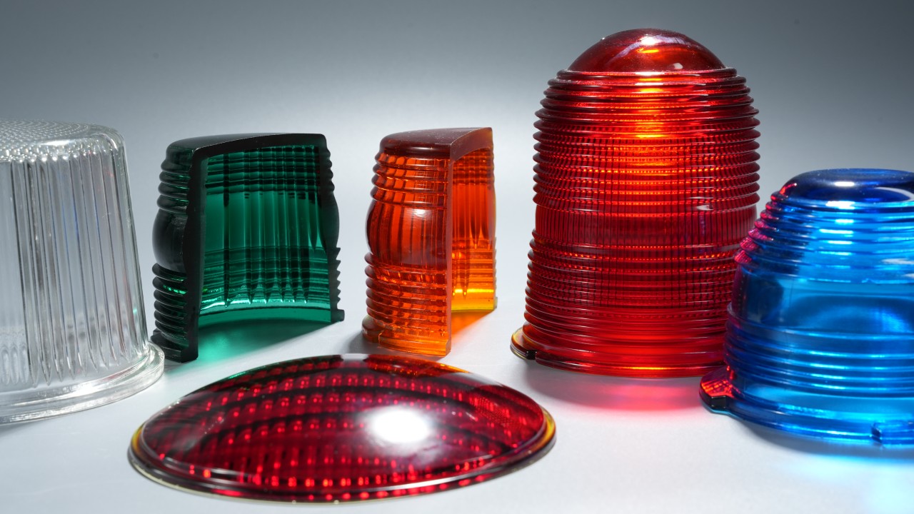
Image disclaimer: For identification and illustration only. It may show a product by another manufacturer and may not depict the exact item described; it is not a statement of any product’s quality, approval or performance. Third-party image and trademark rights belong to their owners. See full notice.
What Is It?
The Beacon Lens Assembly is the optical subsystem of a rotating beacon, responsible for shaping, directing, and colouring the light emitted by the source (lamp or LED). It typically consists of one or more optical lenses, dichroic or glass colour filters (e.g., green, white, yellow), a parabolic or faceted reflector, and a mounting frame that aligns these components precisely with the light source. The assembly is mounted on the rotating turntable and rotates with it, producing the sweeping beam and alternating colour sequence. The optical design determines the beam width, intensity distribution, and colour purity—all critical for meeting ICAO and FAA photometric requirements. Modern assemblies may use dichroic filters that reflect unwanted wavelengths and transmit the desired colour, minimizing heat absorption and improving efficiency.
Purpose & Function
The lens assembly exists to turn a raw light source into the specific, regulated visual signal that gives a beacon its meaning: without precise colour filtering and beam shaping, a bright light source alone would communicate nothing more than "something is here," rather than the airport-versus-heliport, land-versus-water distinctions that specific colour sequences are designed to convey. Its optical precision matters because ICAO and FAA photometric standards specify not just colour but beam width and intensity distribution, so the assembly's design directly determines whether the beacon meets its certified visibility distance and colour purity requirements. The move toward dichroic filters in modern assemblies reflects this same purpose taken further: by reflecting unwanted wavelengths rather than absorbing them, the assembly reduces heat buildup on the optics, improving both efficiency and the long-term reliability of the colour signal the beacon depends on.
Where Is It Used?
Used in rotating identification beacons: civil land airport beacons (white/green), heliport beacons (white/green/yellow, three-colour sequence), water airport beacons (white/yellow), and military airport beacons (white/white/green). The lens assembly is a critical replaceable component; different colour combinations can be achieved by changing the filter set, allowing the same mechanical beacon to be adapted for different applications. Used in both halogen and LED beacon designs, with LED‑specific optics designed for the different light distribution patterns of LEDs. Note that obstruction lights (typically red at night, white by day) are a separate fixture category — usually a fixed or omnidirectional strobe rather than a rotating multi-segment beacon — and are not normally built around this same lens assembly.
Installation & Location
The lens assembly is mounted on the beacon's rotating turntable, aligned precisely with the light source (lamp or LED module) so the reflector and filters sit at the correct focal position to produce the certified beam width and intensity distribution. Mounting uses a machined frame that locates the reflector, filters, and any secondary lenses to a fixed reference, since even small misalignment can distort the beam pattern or shift the colour transition points pilots rely on. The assembly is installed as a unit during beacon manufacture or servicing, and is designed to be removed and replaced independently of the motor and turntable so filters or optics can be swapped without disturbing the drive mechanism. Photometric verification is carried out after installation or filter replacement to confirm the beam still meets the applicable ICAO or FAA intensity and colour requirements.
How Does It Work?
The lens assembly works by collecting light from the lamp or LED array and collimating it into a narrow horizontal beam (typically 3–5° wide) using a parabolic or ellipsoidal reflector. The beam passes through a colour filter (e.g., green) and then through a lens that shapes the vertical beam spread (typically 5–10°) to ensure visibility from aircraft at various approach angles. The assembly is mounted on the rotating turntable; as it rotates, the beam sweeps 360° horizontally. The filter is split into two or more segments (e.g., 180° green and 180° white) so that as the assembly rotates, an observer sees alternating colours. The entire assembly is housed in a weatherproof enclosure with a transparent dome (which may also act as a lens). The optical surfaces are coated with anti‑reflective and UV‑resistant coatings to maintain performance over time.
System Architecture & Control Logic
The beacon's control chain has two independent halves that must both succeed for the signal to be valid: an on/off decision and a rotation guarantee. A photocell or astronomical timer (often backed up by an ALCMS override for IFR conditions or a NOTAM-driven schedule) decides whether the beacon should be running at all. Once enabled, a dedicated beacon controller starts the synchronous drive motor, which turns the turntable at a fixed rate so the alternating colour segments sweep past an observer at the correct flash frequency — the rotation rate itself is the "signal timing," so a motor that runs slow or stalls degrades the beacon even while the lamp stays lit. In parallel, the lamp/LED driver energizes the light source; on twin-lamp beacons, an automatic lamp changer switches to the standby filament the instant the primary fails, so a single burned-out lamp does not extinguish the beacon. Because an unobserved beacon failure has real safety consequences, most installations feed lamp-failure and rotation-failure status back to a remote alarm panel or the ALCMS rather than relying on visual inspection alone.
Photocell / Timer → Beacon Controller → Drive Motor + Lamp Driver → Rotating Lens (with fault feedback)
Optical Path & Colour Sequencing
The colour filter is split into segments (e.g. 180° green / 180° white) — as the turntable rotates, each segment passes through the beam in turn
Physical Construction
The lens assembly combines an aspheric or Fresnel collimating lens, moulded from borosilicate glass or optical-grade acrylic, with a dichroic interference filter or dyed-glass colour filter bonded or clamped in front of it to produce the required beam colour. A polished aluminium or coated-glass parabolic reflector sits behind the lamp or LED source to concentrate and redirect emitted light forward through the lens, with anti-reflective coatings applied to lens surfaces to maximise luminous efficiency. The complete optical stack is retained within a machined metal or high-strength composite bezel that mounts to the beacon's rotating turntable, with UV-resistant and anti-static coatings applied to the outer lens face to resist yellowing and dust accumulation over years of outdoor service. Gasketed seals between the lens, bezel, and housing maintain a weatherproof barrier around the optical chamber, and the assembly is designed for tool-free or quick-release removal to simplify lamp replacement and periodic cleaning.
Technical Parameters
| Parameter | Typical Value |
|---|---|
| Lens Type | Aspheric or Fresnel (collimating) |
| Lens Material | Borosilicate glass or optical acrylic |
| Filter Type | Dichroic (interference) or dyed glass |
| Colour Options | Green, White, Yellow (per ICAO/FAA identification beacon combinations) |
| Beam Width (Horizontal) | 3°–5° (depending on design) |
| Beam Width (Vertical) | 5°–10° (for aircraft visibility) |
| Reflector Type | Parabolic (polished aluminium or coated glass) |
| Luminous Efficiency | ≥85% (with anti‑reflective coatings) |
| Filter Transmission | >70% for target wavelengths |
| Operating Temperature | -40°C to +85°C |
| Protection | UV‑resistant coatings, anti‑static |
Applicable Standards
ICAO Annex 14
Beacon colour, intensity, and beam spread requirements
FAA AC 150/5345-12
Specification for Airport and Heliport Beacons (covers the lens/filter/optical requirements as part of the complete beacon spec)
IEC/TS 61827
Characteristics of inset and elevated luminaires used on aerodromes and heliports (photometric & electrical performance)
FAA Engineering Brief #67
Light Sources Other than Incandescent and Xenon for Airport and Obstruction Lighting Fixtures
Installation Requirements
Handling & Surface Protection
MechanicalHandle the lens and filter stack with clean gloves and protective wrapping until final fit, avoiding fingerprints, scratches, or dust on the anti-reflective and UV-resistant coatings.
Colour Segment Verification
ConfigurationConfirm the correct colour filter (green, white, or yellow) is fitted in each segment position per the site's beacon colour sequence before final assembly.
Lamp/Reflector Optical Alignment
MechanicalCentre the lamp or LED source at the reflector's focal point and align the lens axis to it, since a misaligned optical stack skews the beam width and reduces effective intensity.
Bezel & Gasket Seating
MechanicalSeat the lens within the bezel and confirm the gasket seal between lens, bezel, and housing is unbroken and evenly compressed to maintain the weatherproof barrier around the optical chamber.
Quick-Release Fixing Check
MechanicalConfirm the tool-free or quick-release retention mechanism engages fully and securely, so the assembly cannot loosen or shift under continuous rotation.
Final Cleaning Before Close-up
MechanicalClean all optical surfaces of installation residue, packaging dust, and handling marks immediately before the housing is closed and the beacon returned to service.
Pre-Energisation Sign-off
DocumentationRecord colour segment configuration, optical alignment, and gasket condition as-built before the beacon is closed up and returned to service.
Testing & Commissioning
Visual & Dimensional Inspection
Pre-InstallationInspect the reflector, lens, and colour filters for damage, delamination, or manufacturing defects, and confirm dimensions match the mounting frame before fitting.
Optical Alignment & Focus Verification
InstallationPosition the reflector and lens at the correct focal distance from the light source, confirming the beam collimates as designed before final fastening.
Colour Filter Segment Registration Check
InstallationConfirm each colour filter segment is correctly registered to the turntable rotation so the colour transition occurs at the intended point in the sweep.
Beam Width & Vertical Spread Verification
Final AcceptanceMeasure horizontal beam width (typically 3–5°) and vertical spread (typically 5–10°) against the design specification.
Photometric Intensity & Transmission Test
Final AcceptanceMeasure beam intensity and colour transmission with a calibrated photometer against ICAO/FAA commissioning tolerances.
Seal & Mounting Torque Check
Final AcceptanceConfirm gaskets are correctly seated and mounting fasteners are torqued to specification to keep the assembly weatherproof and vibration-resistant.
Documentation & As-Built Sign-off
Final AcceptanceRecord alignment, beam geometry, and photometric readings alongside the assembly's part/colour configuration in the commissioning dossier for handover.
Inspection & Maintenance
Photometric & Transmission Check
AnnualVerify filter transmission and beam intensity against spec using a calibrated photometer; degraded output usually points to filter fade, hazing, or reflector tarnishing.
Optical Surface Cleaning
QuarterlyClean lens and reflector surfaces with approved optics-safe solutions to remove salt, dust, and chemical residue before it etches or hazes the optics.
Colour Filter Inspection
AnnualCheck dyed glass filters for UV-driven colour shift and dichroic filters for peeling or delamination, replacing as needed to maintain correct colour identification.
Reflector Condition Check
AnnualInspect the parabolic reflector for tarnishing or coating failure, particularly in high-humidity or corrosive environments where replacement may be needed every 5-10 years.
Beam Width Verification
Semi-annualConfirm horizontal and vertical beam spread stay within the specified 3°-5° and 5°-10° ranges, since optical misalignment can narrow or skew coverage.
Seal & Mounting Inspection
AnnualCheck gaskets and mounting hardware securing the assembly to the rotating mechanism, since a failed seal allows moisture ingress that fogs the optics from within.
Anti-Static & Coating Check
AnnualVerify UV-resistant and anti-static coatings remain intact, since coating breakdown accelerates dust adhesion and surface degradation.
Common Field Issues
Filter Degradation (Colour Shift)
Dyed glass filters fade over time due to UV exposure and heat, causing colour shift (e.g., green becoming yellow-green). Dichroic filters are more stable but can peel or delaminate. Regular photometric testing and filter replacement are essential.
Lens Hazing and Surface Etching
Environmental contaminants (salt, dust, chemicals) can etch or haze the optical surfaces, reducing light output and beam quality. Regular cleaning with approved optics‑safe solutions and periodic replacement of the lens is recommended.
Reflector Tarnishing
Aluminium reflectors can tarnish over time, reducing reflectivity. Sealed reflectors with protective coatings are more durable. In high‑humidity or corrosive environments, reflector replacement may be needed every 5–10 years.
Troubleshooting Guide
Colour Beam Shifted or Washed Out
Reduced Light Output / Dim Beam
Fogged or Condensation-Filled Housing
Visible Crack, Chip, or Physical Damage
Failure Modes & Root Causes
Filter Fading / Delamination
Optical Surface Etching or Reflector Tarnish
Seal / Gasket Failure
Impact or Thermal-Shock Damage
Safety & Operational Notes
Rotating Machinery Lockout
Personnel SafetyStop and lock out the turntable drive before reaching into the beacon housing; the lens assembly rotates with the turntable and can cause serious injury if it starts while hands are inside.
Working at Height on the Beacon Tower
Personnel SafetyUse fall protection appropriate to the tower or structure the beacon is mounted on, and follow the site's permit-to-work procedure for elevated tasks.
Hot Lamp / Lens Contact Precaution
Personnel SafetyAllow the lamp and lens assembly to cool before handling after an active period; incandescent sources in particular retain significant heat and can cause burns during filter or reflector replacement.
Careful Handling of Glass/Filter Components
MechanicalHandle dichroic filters and glass lens elements with clean gloves and avoid mechanical stress on the mounting frame; a cracked or chipped filter degrades colour purity and can fail suddenly under further thermal cycling.
Electrical Isolation Before Servicing
Electrical SafetyDe-energise and lock out the beacon's power supply before opening the housing to service the lens assembly, and verify zero energy before handling any wiring.
Engineering & Expert Notes
Verify Colour Purity Directly, Not by Assumption
OpticalEven dichroic filters designed to reflect unwanted wavelengths and reduce heat absorption can shift their colour transmission characteristics after years of thermal cycling; measure actual colour purity against spec periodically rather than assuming the coating performs indefinitely as designed.
Test Intensity Independently of Colour Quality
MaintenanceA parabolic or faceted reflector can lose reflectivity from oxidation or micro-pitting well before the colour filters show any visible wear; test beam intensity as its own check rather than inferring it from a colour-quality inspection.
Alignment Drift Changes Sweep Timing, Not Just Beam Shape
AlignmentA lens assembly slightly out of alignment with the turntable axis can alter the apparent flash rate or sweep pattern seen from a distance, a different symptom than a dim or discoloured beam; verify rotational alignment as its own check rather than relying on beam-quality inspection to catch it.
Inspect Filter Edges for Hairline Cracks
InspectionWhere the mounting frame and glass filters expand at different rates through daily heat cycles, repeated thermal stress can crack a filter even without any impact; check filter edges closely for hairline cracks, which are easy to miss without close inspection.
Check Rotational Balance as Its Own Maintenance Item
MechanicalAn assembly can produce a perfectly good beam while still being slightly out of rotational balance, which accelerates wear on the turntable bearing; check balance directly rather than assuming good optical output means the rotating assembly is in good mechanical condition.
Internal Condensation Signals a Seal Failure Early
DiagnosticsCondensation inside a sealed lens housing indicates a seal failure before optical performance visibly suffers; catching it early prevents the fogging and eventual water damage that would otherwise first appear as a gradual beam-quality complaint.
Frequently Asked Questions
Short answers about beacon lens assemblies: function, colour sequences, optics, standards, maintenance and common faults.
Q1What is a beacon lens assembly?
A beacon lens assembly is the optical subsystem of a rotating beacon. It shapes, directs and colours the light from the lamp or LED, and typically combines one or more lenses, dichroic or glass colour filters (green, white, yellow), a parabolic or faceted reflector, and a mounting frame that holds them aligned with the light source.
Q2Why does a beacon need a lens assembly instead of just a bright light?
Without precise colour filtering and beam shaping, a bright source only says something is there. The lens assembly turns it into a regulated signal, so the colour sequence can tell pilots whether the beacon marks a land airport, a heliport or a water airport.
Q3Which beacons use a lens assembly and what colour sequences do they show?
It is used in rotating identification beacons: civil land airport beacons (white/green), heliport beacons (white/green/yellow three-colour sequence), water airport beacons (white/yellow) and military airport beacons (white/white/green). Changing the filter set lets the same mechanical beacon be adapted to a different colour combination.
Q4How does the lens assembly form the beacon beam?
The reflector collimates light from the source into a narrow horizontal beam, typically 3-5 degrees wide. The beam passes through the colour filter and then a lens that sets the vertical spread, typically 5-10 degrees. The filter is split into segments, for example 180 degrees green and 180 degrees white, so as the turntable rotates an observer sees alternating colour flashes.
Q5What are the typical specifications of a beacon lens assembly?
Typical values are an aspheric or Fresnel collimating lens in borosilicate glass or optical acrylic, a dichroic or dyed-glass filter, a parabolic reflector, luminous efficiency of at least 85% with anti-reflective coatings, filter transmission above 70% at the target wavelengths, and an operating temperature of -40°C to +85°C.
Q6What is the difference between dyed-glass and dichroic colour filters?
Dyed-glass filters fade under UV and heat, for example green shifting toward yellow-green. Dichroic filters are more stable but can peel or delaminate. Either type should be checked with periodic photometric testing rather than assumed to be performing to specification.
Q7Which standards apply to beacon lens assemblies?
The main references are ICAO Annex 14 (beacon colour, intensity and beam spread), FAA AC 150/5345-12 (Specification for Airport and Heliport Beacons), IEC/TS 61827 (luminaire characteristics) and FAA Engineering Brief #67 (light sources other than incandescent and xenon).
Q8How often should a beacon lens assembly be inspected and maintained?
Typical intervals are quarterly for cleaning lens and reflector surfaces, semi-annual for beam width verification, and annual for the photometric and transmission check, colour filter inspection, reflector condition, seal and mounting inspection, and coating checks. Reflectors in humid or corrosive environments may need replacement every 5-10 years.
Q9Why does a beacon's green look yellowish or washed out?
The usual cause is UV and heat fading a dyed-glass filter, or a dichroic coating that has started to peel or delaminate. Run a photometric colour check against the ICAO/FAA chromaticity limits, inspect the filter for fading, crazing or delamination under strong light, and replace the filter if it is out of specification.
Q10What safety precautions apply when working on a beacon lens assembly?
The assembly rotates with the turntable, so stop and lock out the drive before reaching into the housing. Use fall protection appropriate to the tower and follow the permit-to-work system, and handle the lens and filter stack with clean gloves to avoid scratching the coatings.
Related Components
Go Beyond the Component. Understand the Complete AGL System.
You have explored the component. Now understand how it works within the complete Airfield Ground Lighting system.
Learn AGL from fundamentals to design, installation, testing, photometry, commissioning, maintenance and troubleshooting through structured technical training at Precision AGL Academy.
Build practical knowledge. Understand the circuit. Read the standards. Troubleshoot with confidence.
Your next step in AGL starts here.
Need expert guidance on beacon lens assembly selection or refurbishment?
Precision AGL Academy provides advice on optical design, filter technology, and compliance for beacon optical systems.
Follow the Academy
Important Notice, Disclaimer & Limitation of Liability
Please read before relying on any content on this page.
- Purpose and intended users. This page on Beacon Lens Assembly is an independent educational and informational reference for competent, suitably trained and authorised airfield ground lighting (AGL) and aerodrome electrical personnel. It is not professional engineering, legal or regulatory advice, and using it does not create any professional or client relationship.
- Safety. Work on series circuits, constant current regulators (CCRs), isolating transformers, cables, connectors and lighting equipment can be fatal. Always apply the aerodrome’s permit-to-work and isolation/LOTO procedures, prove dead, use correctly rated instruments and PPE, and follow the manufacturer’s instructions. Nothing here authorises work on live equipment or the bypassing of any safety device or interlock.
- Aviation operations. Nothing here authorises installation, modification, energisation, adjustment, return to service, a change of operating category (CAT I/II/III), a NOTAM or any aerodrome certification or approval decision. These rest with the aerodrome operator, the air navigation service provider and the competent regulator.
- Specifications, ratings and typical values. Descriptions, parameters, ratings, dimensions, photometric values, wattages, service lives, maintenance tasks and intervals, failure modes, certifications (for example CE, FCC, UL or IEC marks) and part or type designations are general, typical and indicative. They may not match any particular product, make, model or version, and they are not a datasheet, design, specification, selection, sizing, procurement or acceptance criterion. The manufacturer’s current documents, the approved design and the project specification prevail.
- Standards and regulations. References to ICAO, FAA, IEC, IEEE, ISO, BIS, DGCA and other standards are paraphrased summaries for orientation only. They may be incomplete or out of date, and standards are revised from time to time. Consult the current official editions. Following this content does not guarantee compliance with any law, standard or regulatory approval, and the regulator’s requirements always prevail.
- No warranty. Content is provided “as is” and “as available”, without warranty of any kind, express or implied, including accuracy, completeness, currency or fitness for a particular purpose. Real installations differ in design, equipment make and model, age and condition.
- Limitation of liability. To the fullest extent permitted by applicable law, Precision AGL Academy, Precision AGL Solutions and their owners, authors and contributors are not liable for any injury, death, loss, damage, downtime, penalty or regulatory consequence, whether direct or indirect, arising from the use of, reliance on, or inability to use this content. Nothing in this notice excludes or limits any liability that cannot lawfully be excluded or limited.
- Independence, brands and no endorsement. This is an independent publication. It is not affiliated with, sponsored by or endorsed by ICAO, the FAA, the IEC, DGCA, AAI, any airport, regulator, supplier or equipment manufacturer. Third-party names, product designations, standard designations and trademarks (including Megger®, Siemens, Eaton, Crouse-Hinds, ADB SAFEGATE, Fluke, ABB and Honeywell) belong to their respective owners and are used only for identification and description. Mention of a brand, product or supplier is not a recommendation, and we do not sell, supply or quote for any component described.
- Images and third-party content. Images and illustrations are shown to help identify the type of component. They may show products of various manufacturers, may not depict the exact item described, and are not a statement about any product’s quality, approval or performance. Copyright and trademarks in third-party images, logos and photographs belong to their respective owners and are not claimed as ours. If you are a rights holder and want an image removed, replaced or credited, email precisionaglsolutions@gmail.com with the page address and we will act promptly.
- Training and services. Mentions of training, courses, consultation, advice, selection, installation, calibration or other support, including the “Learn…Certify” pathway, describe learning stages and are not an offer, quotation, tender or promise of any result. Contacting us or our replying creates no engagement or duty of care; an engagement exists only under a written agreement. We are not a regulator or certification body, and completing any course or reading this content is not a certification, accreditation or authorisation to work on any aerodrome.
- Copyright, privacy and corrections. © 2026 Precision AGL Academy. All rights reserved. Text, structure, compilations and diagrams may be viewed for personal reference and internal training only; any other copying, republication or commercial use needs our written permission. If you email, telephone or message us, we use your details only to respond and handle your matter, in line with applicable Indian law including the Digital Personal Data Protection Act, 2023; please do not send confidential or security-sensitive information. To display this page your browser requests fonts, icons and images from third-party servers, which receive your IP address and browser details under their own policies. Content is reviewed periodically with no obligation to update. To report an error, safety concern or rights issue, write to precisionaglsolutions@gmail.com.