AT‑VASIS
Abbreviated T‑Visual Approach Slope Indicator System – a 10-light, all-white glide slope system: a single-side wing bar plus a bisecting "fly-up"/"fly-down" line, reproducing the T-VASIS graduated indication with half the unit count and on one side of the runway only, normally set to the standard 3° glide path (adjustable up to around 4° where a steeper approach is specifically required), making it suitable for smaller airfields, heliports, and military forward operating bases where a full T‑VASIS is not justified.
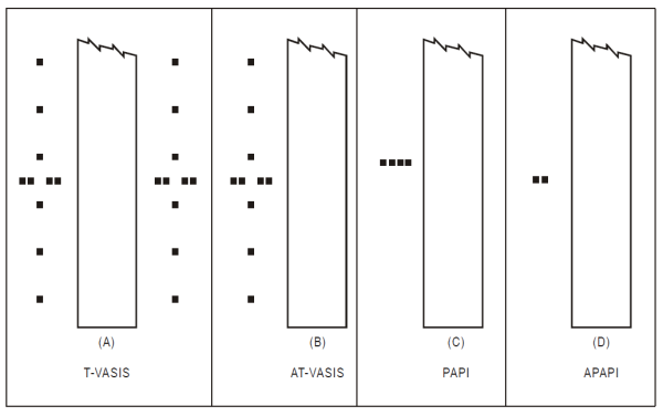
Image disclaimer: For identification and illustration only. It may show a product by another manufacturer and may not depict the exact item described; it is not a statement of any product’s quality, approval or performance. Third-party image and trademark rights belong to their owners. See full notice.
What Is It?
The Abbreviated T‑Visual Approach Slope Indicator System (AT‑VASIS) is a compact visual glide slope guidance system built from ten light units, all of which emit white light in normal operation — like full T‑VASIS, it does not rely on a red/white colour split. Where full T‑VASIS mirrors its wing bar and fly line on both sides of the runway (20 units total), AT‑VASIS installs a single wing bar of four lights plus one bisecting fly line of six lights on one side only, halving the unit count while keeping the same graduated, number-of-lights signal.
AT‑VASIS reads the same way as full T‑VASIS: the wing bar alone means on path, and progressively more fly-down or fly-up lights show how far above or below the aircraft is. Like T‑VASIS, it is normally set to the standard 3° glide path used by VASI and PAPI, and — like any VGSI — can be adjusted up to around 4° at airfields with obstacle clearance constraints or noise abatement requirements.
Purpose & Function
AT-VASIS exists to make the graduated, T-shaped glide-path guidance of T-VASIS available to airfields that can't justify the cost or space of the full installation. By trimming the number of light units while keeping the distinctive T-shaped visual cue, it preserves the core benefit of the design — a precise, intuitive read on descent angle — at the standard 3° path, or steepened up to around 4° at sites facing obstacle clearance limits or noise abatement requirements.
Because pilots read the T-shape as a single visual pattern rather than tallying individual light colours, the abbreviated version still delivers a fast, unambiguous sense of high, low, or on-path even with fewer units, which is what makes it a workable lower-cost alternative rather than a compromised one.
Where Is It Used?
AT‑VASIS is deployed on a variety of airfields where a steeper glide path and a compact system are required:
- Military forward operating bases – where rapid deployment and compact footprint are essential.
- Smaller commercial airfields – with obstacle clearance or noise abatement requirements.
- Heliports – where a steeper approach angle is beneficial for helicopter operations.
- Regional airstrips – with limited electrical infrastructure and space.
- As a backup or supplement to ILS – on larger runways for additional visual guidance.
- Airfields serving turboprop and regional jet aircraft – that benefit from steeper approach profiles.
Installation & Location
AT-VASIS uses a reduced light-bar arrangement mounted on one side of the runway, set back from the threshold at the distance needed to place the glide path over the threshold at the correct height, and tied into the runway centreline and threshold survey. Bars sit on frangible mounts at a fixed lateral offset from the runway edge, clear of the obstacle-limitation surface, with each bar individually levelled and aimed during commissioning to reproduce the standard T-VASIS visual cues from a smaller unit count. Cabling is run underground from each bar back to its constant current regulator, and the reduced footprint compared to full T-VASIS allows installation on narrower strips or sites with tighter clearance margins, while still requiring the same setting-out discipline against the runway survey.
How Does It Work?
AT‑VASIS operates on a fundamentally different principle from PAPI and VASI, the same as full T‑VASIS: instead of a colour transition, it signals deviation through which and how many white lights are illuminated, with red reserved only as a severe-deviation warning — just with half the unit count of the full system. The system consists of:
- Configuration: Ten light units on one side of the runway: a single "wing bar" of four lights running across the approach direction, and one bisecting longitudinal "fly line" of six lights running down the approach path. All units project white light in normal operation.
- Colour Indication: The pilot reads the number of illuminated lights, not a colour split:
- On the correct glide path: Only the wing bar is visible, steady white. No fly-up or fly-down lights are lit.
- Above the glide path: The wing bar plus one, two, or three "fly-down" lights are visible — the more fly-down lights lit, the further above the slope.
- Below the glide path: The wing bar plus one, two, or three "fly-up" lights are visible — the more fly-up lights lit, the further below the slope.
- Well below the glide path: The wing bar and fly-up lights change from white to red as a distinct, higher-severity warning that the aircraft is significantly low.
- Configurable Approach Angle: Like T‑VASIS, AT‑VASIS is normally set to the standard 3° glide path and can be set up to around 4° where obstacle clearance requires it.
- Power and Control: AT‑VASIS units are powered from the constant current series circuit via isolating transformers, with intensity controlled by the CCR (typically 3‑step).
- Integration: AT‑VASIS is typically deployed independently or integrated with the runway lighting system.
System Architecture & Control Logic
AT‑VASIS carries the same fixed-optics control logic as full T‑VASIS, just with one wing bar and one fly line instead of two of each. The wing-bar units are aimed to appear steady white only near the correct glide-path angle. Each fly-line unit's lens/reflector is tilted at commissioning so it switches on at a specific elevation deviation from the design glide path, with the six units spaced along the line so that, together, they show progressively more fly-down lights above the design glide path and progressively more fly-up lights below it — the fly-up units also switch from white to red once the deviation passes a severe-low threshold, exactly as on the full system. That optical aim is fixed hardware, re-verified by ground or flight check — no processor decides which unit lights up. Both the wing bar and the fly line draw from the same constant current series circuit through their own isolating transformers, and the CCR (typically a basic 3‑step unit) sets one shared brightness level for the whole array. Loop-level fault monitoring is standard series-circuit practice: a voltage rise at constant current flags an open lamp or failed transformer as a loop fault, without pinpointing which unit is affected until sectionalised testing is done.
CCR (3‑step) → Series Circuit Loop → Isolating Transformer → Wing Bar (4 units) & Fly Line (6 units)
What "Abbreviated" Actually Means
AT‑VASIS keeps the full six-unit fly line and four-unit wing bar used on full T‑VASIS — the abbreviation comes from installing that wing-bar-plus-fly-line group on one side of the runway only (10 units total) instead of mirroring it on both sides (20 units). Same unit design, same optical principle, half the installation.
Physical Construction
Each unit is an individual box-section housing in die-cast aluminium alloy or louvred galvanised steel, built the same way as a full T-VASIS fixture and installed as the same wing-bar-plus-fly-line group, but on one side of the runway only rather than mirrored on both — the abbreviation for lower-traffic runways that don't warrant the complete, symmetric system. Optics are shaped as a lens/reflector assembly tuned to the fixture's role in the array, with a built-in levelling and pitch-adjustment mechanism used to aim each unit precisely to the set glide-path angle during commissioning. Every unit mounts on its own frangible mast at a fixed, surveyed height, engineered to shear away cleanly if struck, and is wired individually so the control system can switch fly-up or fly-down units independently as needed. Cabling runs underground in conduit to isolating transformers housed in nearby base cans, with sealed, direct-burial connectors and a drainage provision to keep the transformers and cable entries free of standing water.
Technical Parameters
| Parameter | Typical Value |
|---|---|
| Light Source | LED array or 45W/65W halogen lamp |
| Colour | White (all units in normal operation); fly-up units switch to red only as a severe-below-path warning |
| Luminous Intensity | Up to 12,000 cd (white) and 6,000 cd (red, fly-up severe-deviation state) depending on setting |
| Intensity Steps | 3‑step (day, twilight, night) or 5‑step (2.8A – 6.6A) CCR controlled |
| Glide Path Angle | Typically 3° (same as PAPI/VASI); adjustable up to ~4° for site-specific obstacle/noise requirements |
| Beam Pattern | Narrow vertical beam per unit; signal is which/how many units are lit, not a per-unit colour transition |
| Configuration | Wing bar (4 units) + bisecting fly line (6 units), one side of the runway only |
| Number of Units | 10 units total (half of full T‑VASIS's 20, which mirrors the same group on both sides) |
| Mounting Type | Elevated (frangible poles) – typically 10–20 m from runway edge |
| Isolating Transformer | 45W – 65W (6.6A series circuit) per unit |
| Protection Class | IP67 / IP68 (weather‑resistant) |
| Operating Temperature | -40°C to +55°C |
Electrical Requirements
| Requirement | Typical Value |
|---|---|
| Circuit Type | Series circuit, constant current (CCR fed) |
| Rated Series Current | 6.6A (5-step: 2.8A / 3.4A / 4.1A / 5.2A / 6.6A) or 3-step equivalent |
| Isolation | Via dedicated isolating transformer (45W/65W) per unit |
| Circuit Configuration | Wing-bar and fly-line units wired to hold a synchronised intensity step across the array |
| Transformer Secondary | Matched to fixture wattage; sized to series circuit rating |
| Cable Type | L-824 single-conductor, direct-burial rated, 5kV or 600V per circuit design |
| Connector | L-823 primary connector, submersible-rated splice |
| Insulation Resistance | ≥ 50 MΩ (megger test, cable-to-ground) |
| Earthing/Grounding | Fixture body and base can bonded to airfield earth grid |
| Fault Protection | CCR-level ground fault and open-circuit detection |
| Power Source | CCR output, regulated per ICAO/FAA intensity step schedule |
Photometric Requirements
| Parameter | Typical Value |
|---|---|
| Main Beam Intensity (White) | ≥ 9,000 cd on-axis per unit, up to 12,000 cd at full intensity |
| Main Beam Intensity (Red) | ≥ 4,500 cd on-axis per unit, up to 6,000 cd at full intensity |
| Switch-On Sharpness | ≤ 4 arc-minutes vertical transition band per fly-line unit (angle at which each unit switches on, not a colour transition) |
| Vertical Beam Spread | 6-unit fly line spaced about the design glide-path reference (typically 3°, adjustable up to ~4° where required); wing bar fixed at the on-slope reference angle |
| Horizontal Beam Spread | ± 5° to ± 10° either side of runway centreline plane |
| Isocandela Distribution | Per ICAO Annex 14 Attachment A / relevant national civil aviation authority T-VASIS figures |
| Chromaticity (White) | Within ICAO Annex 14 white boundary (CIE coordinates) |
| Chromaticity (Red) | Within ICAO Annex 14 red boundary (CIE coordinates) |
| Intensity Tolerance | ± 25% of rated value at each CCR step (field measurement) |
| Maintenance Factor | ≥ 50% of new-fixture intensity before lamp/lens replacement is due |
| Test Method | Mobile photometric van/goniophotometer or fixed test bench per unit |
Applicable Standards
ICAO Annex 14
Guidance for abbreviated visual slope indicators including AT‑VASIS
FAA AC 150/5340-25
Visual Approach Slope Indicator (VASI) Systems – closest FAA equivalent guidance; AT‑VASIS is primarily governed outside the US by ICAO Annex 14 and national CAAs
UK CAA CAP 168
Licensing of aerodromes – AT‑VASIS requirements
IEC/TS 61827
Characteristics of inset and elevated luminaires used on aerodromes and heliports (photometric & electrical performance)
Installation Requirements
Reduced Array Setout
CivilTie the shortened bar arrangement to the runway centreline and threshold survey at the distance needed to place the glide path over the threshold at the correct height.
Frangible Pole Foundations
CivilInstall footings for each bar within the tighter clearance margins typical of the narrower strips AT-VASIS is used on.
Duct & Cable Route to CCR
ElectricalRun underground cabling from each bar back to its constant current regulator.
Isolating Transformer Matching
ElectricalConfirm each unit's 45W–65W isolating transformer matches the series circuit's rated current step before connection.
Unit-by-Unit Aiming & Levelling
MechanicalIndividually level and aim each bar during commissioning to reproduce the standard T-VASIS visual cues from the smaller unit count.
Frangible Coupling Fixing
MechanicalTorque frangible pole couplings to the specified value across the reduced array.
Narrow-Strip Clearance Check
DocumentationVerify the reduced footprint fits within the available clearance margins at sites too tight for full T-VASIS.
Pre-Energisation Sign-off
DocumentationRecord survey coordinates, cable routes, and torque values for every bar as-built before the site is closed.
Testing & Commissioning
Insulation Resistance (Megger) Test
Pre-EnergisationMegger-test each unit's isolating transformer and the series loop before energisation, confirming insulation resistance clears the acceptable minimum ahead of backfill.
Loop Continuity & Resistance Test
Pre-EnergisationVerify series loop continuity end to end across the wing-bar and fly-line units and record total loop resistance, ruling out open circuits or high-resistance splices before first energisation.
Primary/Secondary Voltage Verification
EnergisationWith the CCR energised, confirm secondary voltage at each unit's connector matches the transformer's rated ratio at the commissioned current step.
Independent Switching Verification
EnergisationConfirm each fly-up and fly-down unit switches independently under control system command, since correct glide-path indication depends on individual units illuminating in the right combination even with the reduced unit count.
Glide Path Angle Verification
Final AcceptanceSet each unit's aiming angle with a calibrated aiming tool or theodolite to the design glide-path angle (typically 3°, or the site-specific angle up to ~4° where set steeper), confirming the wing bar and fly line together present the correct on-slope, fly-up, and fly-down pattern from the approach.
Photometric Commissioning Test
Final AcceptanceMeasure beam intensity, colour, and transition sharpness on each unit with a calibrated photometer against ICAO/FAA commissioning tolerances.
Frangibility & Mounting Verification
Pre-EnergisationConfirm each unit's frangible mast shear point, base height, and surveyed position meet as-built tolerances before the site is finally backfilled.
Documentation & As-Built Sign-off
Final AcceptanceRecord insulation, continuity, voltage, switching logic, and photometric readings for all units alongside as-built position and aiming angles in the commissioning dossier.
Inspection & Maintenance
Wing Bar & Fly-Line Alignment Check
AnnualCalibrate both the wing-bar and fly-line units with precision optical tools, since accurate alignment of both remains critical despite the single-side configuration.
Photometric Intensity Check
AnnualVerify white beam intensity across the wing bar and fly line, and red beam intensity on the fly-up severe-deviation state, against ICAO thresholds using a calibrated photometer.
Lens Cleaning
QuarterlyClean dust, rubber deposits, and de-icing fluid residue from each unit's lens to maintain colour transition integrity.
Lamp / LED Module Inspection
Semi-annualCheck each unit's light source for failure; with fewer units than full T-VASIS a single failure is less severe but still worth prompt replacement.
Frangible Coupling Check
AnnualInspect couplings for fatigue from wind loading and thermal cycling and replace on schedule to preserve breakaway performance.
Insulation Resistance Test
AnnualMegger-test each unit's isolating transformer and series circuit to confirm insulation resistance stays above the minimum, flagging moisture ingress before it causes a fault.
Cable & Connector Inspection
AnnualExamine primary and secondary cable connections for corrosion or loose crimps, a common source of intermittent series-circuit faults.
Mounting Pole Inspection
AnnualCheck pole verticality and base condition for each unit in the wing bar and fly line to ensure the indication stays correctly positioned.
Common Field Issues
Alignment Calibration
AT‑VASIS requires precise calibration of both the wing-bar and fly-line units. Being on one side only doesn't reduce alignment complexity compared to full T‑VASIS — the same accuracy is still critical for correct glide path indication. Regular calibration using precision optical tools is essential.
Lens Contamination
Dust, rubber deposits, and de‑icing fluids can reduce light output and affect the colour transition. Routine cleaning and photometric testing are required to maintain the integrity of the indication.
Lamp or LED Module Failure
With fewer units than full T‑VASIS, the impact of a single failure is less severe, but regular inspections and prompt replacement are still necessary.
Frangible Coupling Fatigue
AT‑VASIS units are mounted on frangible poles. Wind loading and thermal cycling can weaken couplings. Regular inspection ensures breakaway performance on impact.
Pilot Familiarity
Like T‑VASIS, the T‑shaped indication is less familiar than PAPI or VASI. Airfields using AT‑VASIS should ensure pilots are aware of the system and its interpretation.
Troubleshooting Guide
Wing-Bar or Fly-Line Unit Dark, Others Normal
Entire Series Circuit Dark / CCR Will Not Regulate
CCR Trips on Overcurrent or Ground Fault
Incorrect or Ambiguous Indication
Reduced or Hazy Light Output
Unit Leaning, Loose, or Misaligned
Failure Modes & Root Causes
LED Module / Lamp Failure
Isolating Transformer Failure
Wing-Bar or Fly-Line Unit Elevation Drift
Series Cable / Connector Insulation Breakdown
Lens Contamination or Erosion
Frangible Coupling Fatigue
Safety & Operational Notes
Series Circuit Isolation
Electrical SafetyThe wing-bar and fly-line units run on a constant-current series circuit that can carry several kV across the loop. De-energise and lock out the CCR, then verify zero energy at the fixture before opening a base can or handling cable connectors.
Airside Work Coordination
OperationalAny work on or near an active runway requires ATC/airside coordination and a NOTAM while a unit is dark or out of tolerance; with only one side installed, a single out-of-service light has a larger effect on the readable indication than it would on a full T-VASIS array.
Frangibility Not to Be Defeated
MechanicalNever substitute the frangible coupling with a rigid fitting or over-torque it during installation or repair; the coupling must still shear cleanly on aircraft impact to limit damage under the frangibility requirement.
Verify Full Indication Before Return to Service
OperationalAfter maintenance touching any wing-bar or fly-line unit, confirm the complete on-slope/fly-up/fly-down indication reads correctly from the approach; the single-side array leaves less margin to absorb a single unit's aiming error than a full T-VASIS installation.
FOD Control at the Base Can
OperationalKeep tools, fasteners, and removed gaskets accounted for at all times when the base can is open, and secure or remove any loose material before reinstating the fixture, to prevent foreign object debris on the movement area.
Insulation Test Before Re-Energisation
Electrical SafetyAfter any cable, connector, or transformer work, megger test the affected series loop before restoring power, since a residual fault at re-energisation can trip the CCR or damage other units on the same circuit.
PPE & Grounding
Personnel SafetyUse insulated tools and appropriate PPE when working on series-circuit connections, and confirm the fixture and base can are bonded/grounded per the electrical design before reconnecting the loop.
Restore to Compliant State
ComplianceDo not leave a wing-bar or fly-line unit out of aim tolerance, at reduced intensity, or otherwise non-compliant after maintenance; verify photometric and positional conformance on the full array before closing out the work and cancelling the associated NOTAM.
Engineering & Expert Notes
Fly-Down Redundancy Is Halved on the Single-Side Array
DesignThe full T-VASIS relies on its mirrored fly lines on both sides to give advance warning of a gross below-path deviation; AT-VASIS's single fly line gives pilots less redundancy before a large deviation shows, so keep the wing-bar units within tighter tolerance to compensate.
Confirm the Aim Jig Is Set for the Site's Actual Angle
AlignmentWhere a site has set AT-VASIS to a steeper angle (up to around 4°) instead of the standard 3° for obstacle or noise reasons, using an alignment tool left at its default 3° setting is a common site error; confirm the jig or theodolite is configured for the site-specific angle before any adjustment.
Angle Drift Has Compliance Weight, Not Just Photometric Weight
ComplianceWhere the steeper angle exists specifically for obstacle clearance or noise abatement, any post-settling angle drift matters beyond the usual visual glide path tolerance; document angle verification against the original obstacle assessment, not just as a routine photometric pass/fail.
Single-Side Array Makes Each Unit More Visible
MaintenanceWith only one side installed, losing a single light unit changes the perceived pattern more noticeably than the same loss would on a full, mirrored T-VASIS; prioritise fly-line unit faults over wing-bar faults when triaging a reported outage, since the fly-line lights carry the graduated deviation information.
Military-Pattern Sites May Run Non-Standard Power Infrastructure
ElectricalAT-VASIS deployed at military airfields sometimes runs on non-standard voltage or frequency infrastructure; verify transformer and CCR compatibility with the actual site supply rather than assuming civil AGL power standards apply.
Log Angle and Intensity as Two Separate Check Items
VerificationBecause the reduced unit count is a defining feature of AT-VASIS, and the angle may have been steepened for a site-specific reason, angle verification and intensity verification should be tracked as distinct line items at each visit rather than folded into a single general pass/fail.
Frequently Asked Questions
Short answers about the AT-VASIS (Abbreviated T-Visual Approach Slope Indicator System): what it is, how it works, typical specifications, standards, maintenance and common faults.
Q1What is an AT-VASIS (Abbreviated T-Visual Approach Slope Indicator System)?
The Abbreviated T‑Visual Approach Slope Indicator System (AT‑VASIS) is a compact visual glide slope guidance system built from ten light units, all of which emit white light in normal operation — like full T‑VASIS, it does not rely on a red/white colour split.
Q2What is the purpose of an AT-VASIS (Abbreviated T-Visual Approach Slope Indicator System)?
AT-VASIS exists to make the graduated, T-shaped glide-path guidance of T-VASIS available to airfields that can't justify the cost or space of the full installation. By trimming the number of light units while keeping the distinctive T-shaped visual cue, it preserves the core benefit of the design — a precise, intuitive read on descent angle — at the standard 3° path, or steepened up to around 4° at sites facing obstacle clearance limits or noise abatement requirements.
Q3Where is an AT-VASIS (Abbreviated T-Visual Approach Slope Indicator System) used and installed?
AT‑VASIS is deployed on a variety of airfields where a steeper glide path and a compact system are required: Military forward operating bases – where rapid deployment and compact footprint are essential. Smaller commercial airfields – with obstacle clearance or noise abatement requirements. Heliports – where a steeper approach angle is beneficial for helicopter operations. Regional airstrips – with limited electrical infrastructure and space. As a backup or supplement to ILS – on larger runways for additional visual guidance. Airfields serving turboprop and regional jet aircraft – that benefit from steeper approach profiles.
Q4How does an AT-VASIS (Abbreviated T-Visual Approach Slope Indicator System) work?
AT‑VASIS operates on a fundamentally different principle from PAPI and VASI, the same as full T‑VASIS: instead of a colour transition, it signals deviation through which and how many white lights are illuminated , with red reserved only as a severe-deviation warning — just with half the unit count of the full system.
Q5What are the typical technical parameters of an AT-VASIS (Abbreviated T-Visual Approach Slope Indicator System)?
Typical values are — Light Source: LED array or 45W/65W halogen lamp; Colour: White (all units in normal operation); fly-up units switch to red only as a severe-below-path warning; Luminous Intensity: Up to 12,000 cd (white) and 6,000 cd (red, fly-up severe-deviation state) depending on setting; Intensity Steps: 3‑step (day, twilight, night) or 5‑step (2.8A – 6.6A) CCR controlled; Glide Path Angle: Typically 3° (same as PAPI/VASI); adjustable up to ~4° for site-specific obstacle/noise requirements; Beam Pattern: Narrow vertical beam per unit; signal is which/how many units are lit, not a per-unit colour transition.
Q6What are the electrical requirements for an AT-VASIS (Abbreviated T-Visual Approach Slope Indicator System)?
Typical requirements are — Circuit Type: Series circuit, constant current (CCR fed); Rated Series Current: 6.6A (5-step: 2.8A / 3.4A / 4.1A / 5.2A / 6.6A) or 3-step equivalent; Isolation: Via dedicated isolating transformer (45W/65W) per unit; Circuit Configuration: Wing-bar and fly-line units wired to hold a synchronised intensity step across the array; Transformer Secondary: Matched to fixture wattage; sized to series circuit rating; Cable Type: L-824 single-conductor, direct-burial rated, 5kV or 600V per circuit design; Connector: L-823 primary connector, submersible-rated splice; Insulation Resistance: ≥ 50 MΩ (megger test, cable-to-ground).
Q7What photometric requirements apply to an AT-VASIS (Abbreviated T-Visual Approach Slope Indicator System)?
Typical requirements are — Main Beam Intensity (White): ≥ 9,000 cd on-axis per unit, up to 12,000 cd at full intensity; Main Beam Intensity (Red): ≥ 4,500 cd on-axis per unit, up to 6,000 cd at full intensity; Switch-On Sharpness: ≤ 4 arc-minutes vertical transition band per fly-line unit (angle at which each unit switches on, not a colour transition); Vertical Beam Spread: 6-unit fly line spaced about the design glide-path reference (typically 3°, adjustable up to ~4° where required); wing bar fixed at the on-slope reference angle; Horizontal Beam Spread: ± 5° to ± 10° either side of runway centreline plane.
Q8Which standards apply to an AT-VASIS (Abbreviated T-Visual Approach Slope Indicator System)?
The main references are ICAO Annex 14 — Guidance for abbreviated visual slope indicators including AT‑VASIS; FAA AC 150/5340-25 — Visual Approach Slope Indicator (VASI) Systems – closest FAA equivalent guidance; AT‑VASIS is primarily governed outside the US by ICAO Annex 14 and national CAAs; UK CAA CAP 168 — Licensing of aerodromes – AT‑VASIS requirements; IEC/TS 61827 — Characteristics of inset and elevated luminaires used on aerodromes and heliports (photometric & electrical performance). Always verify the current edition and your aerodrome's approved requirements.
Q9How often should an AT-VASIS (Abbreviated T-Visual Approach Slope Indicator System) be inspected and maintained?
Typical maintenance tasks and intervals are: Wing Bar & Fly-Line Alignment Check (annual); Photometric Intensity Check (annual); Lens Cleaning (quarterly); Lamp / LED Module Inspection (semi-annual); Frangible Coupling Check (annual); Insulation Resistance Test (annual); Cable & Connector Inspection (annual); Mounting Pole Inspection (annual). Your airport's approved maintenance programme takes precedence.
Q10How do I troubleshoot common AT-VASIS (Abbreviated T-Visual Approach Slope Indicator System) faults?
Common symptoms covered are: Wing-Bar or Fly-Line Unit Dark, Others Normal; Entire Series Circuit Dark / CCR Will Not Regulate; CCR Trips on Overcurrent or Ground Fault; Incorrect or Ambiguous Indication; Reduced or Hazy Light Output; Unit Leaning, Loose, or Misaligned. For example, for "Wing-Bar or Fly-Line Unit Dark, Others Normal": Likely Cause: Failed LED module / lamp in that unit, or an open isolating transformer feeding it. Diagnostic Steps: Confirm series loop continuity through the affected unit's transformer primary; megger the transformer; check secondary voltage at the connector with the CCR energised. Corrective Action: Replace the failed lamp/LED module if the transformer checks healthy; otherwise swap the isolating transformer and re-seal the connectors before backfill.
Related Components
Go Beyond the Component. Understand the Complete AGL System.
You have explored the component. Now understand how it works within the complete Airfield Ground Lighting system.
Learn AGL from fundamentals to design, installation, testing, photometry, commissioning, maintenance and troubleshooting through structured technical training at Precision AGL Academy.
Build practical knowledge. Understand the circuit. Read the standards. Troubleshoot with confidence.
Your next step in AGL starts here.
Need expert guidance on AT‑VASIS selection, installation, or calibration?
Precision AGL Academy provides advice on glide path design, photometric performance, and field alignment of AT‑VASIS systems for military and civilian applications.
Follow the Academy
Important Notice, Disclaimer & Limitation of Liability
Please read before relying on any content on this page.
- Purpose and intended users. This page on AT‑VASIS is an independent educational and informational reference for competent, suitably trained and authorised airfield ground lighting (AGL) and aerodrome electrical personnel. It is not professional engineering, legal or regulatory advice, and using it does not create any professional or client relationship.
- Safety. Work on series circuits, constant current regulators (CCRs), isolating transformers, cables, connectors and lighting equipment can be fatal. Always apply the aerodrome’s permit-to-work and isolation/LOTO procedures, prove dead, use correctly rated instruments and PPE, and follow the manufacturer’s instructions. Nothing here authorises work on live equipment or the bypassing of any safety device or interlock.
- Aviation operations. Nothing here authorises installation, modification, energisation, adjustment, return to service, a change of operating category (CAT I/II/III), a NOTAM or any aerodrome certification or approval decision. These rest with the aerodrome operator, the air navigation service provider and the competent regulator.
- Specifications, ratings and typical values. Descriptions, parameters, ratings, dimensions, photometric values, wattages, service lives, maintenance tasks and intervals, failure modes, certifications (for example CE, FCC, UL or IEC marks) and part or type designations are general, typical and indicative. They may not match any particular product, make, model or version, and they are not a datasheet, design, specification, selection, sizing, procurement or acceptance criterion. The manufacturer’s current documents, the approved design and the project specification prevail.
- Standards and regulations. References to ICAO, FAA, IEC, IEEE, ISO, BIS, DGCA and other standards are paraphrased summaries for orientation only. They may be incomplete or out of date, and standards are revised from time to time. Consult the current official editions. Following this content does not guarantee compliance with any law, standard or regulatory approval, and the regulator’s requirements always prevail.
- No warranty. Content is provided “as is” and “as available”, without warranty of any kind, express or implied, including accuracy, completeness, currency or fitness for a particular purpose. Real installations differ in design, equipment make and model, age and condition.
- Limitation of liability. To the fullest extent permitted by applicable law, Precision AGL Academy, Precision AGL Solutions and their owners, authors and contributors are not liable for any injury, death, loss, damage, downtime, penalty or regulatory consequence, whether direct or indirect, arising from the use of, reliance on, or inability to use this content. Nothing in this notice excludes or limits any liability that cannot lawfully be excluded or limited.
- Independence, brands and no endorsement. This is an independent publication. It is not affiliated with, sponsored by or endorsed by ICAO, the FAA, the IEC, DGCA, AAI, any airport, regulator, supplier or equipment manufacturer. Third-party names, product designations, standard designations and trademarks (including Megger®, Siemens, Eaton, Crouse-Hinds, ADB SAFEGATE, Fluke, ABB and Honeywell) belong to their respective owners and are used only for identification and description. Mention of a brand, product or supplier is not a recommendation, and we do not sell, supply or quote for any component described.
- Images and third-party content. Images and illustrations are shown to help identify the type of component. They may show products of various manufacturers, may not depict the exact item described, and are not a statement about any product’s quality, approval or performance. Copyright and trademarks in third-party images, logos and photographs belong to their respective owners and are not claimed as ours. If you are a rights holder and want an image removed, replaced or credited, email precisionaglsolutions@gmail.com with the page address and we will act promptly.
- Training and services. Mentions of training, courses, consultation, advice, selection, installation, calibration or other support, including the “Learn…Certify” pathway, describe learning stages and are not an offer, quotation, tender or promise of any result. Contacting us or our replying creates no engagement or duty of care; an engagement exists only under a written agreement. We are not a regulator or certification body, and completing any course or reading this content is not a certification, accreditation or authorisation to work on any aerodrome.
- Copyright, privacy and corrections. © 2026 Precision AGL Academy. All rights reserved. Text, structure, compilations and diagrams may be viewed for personal reference and internal training only; any other copying, republication or commercial use needs our written permission. If you email, telephone or message us, we use your details only to respond and handle your matter, in line with applicable Indian law including the Digital Personal Data Protection Act, 2023; please do not send confidential or security-sensitive information. To display this page your browser requests fonts, icons and images from third-party servers, which receive your IP address and browser details under their own policies. Content is reviewed periodically with no obligation to update. To report an error, safety concern or rights issue, write to precisionaglsolutions@gmail.com.