Apron Flood Light
A high-intensity area lighting system designed to illuminate the aircraft apron, providing bright, uniform illumination for aircraft parking, servicing, and passenger boarding operations. Apron flood lights are essential for safe and efficient ground operations during night and low visibility conditions.
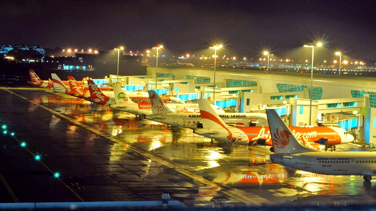
Image disclaimer: For identification and illustration only. It may show a product by another manufacturer and may not depict the exact item described; it is not a statement of any product’s quality, approval or performance. Third-party image and trademark rights belong to their owners. See full notice.
What Is It?
An Apron Flood Light is a high-intensity area lighting system designed to illuminate the aircraft apron, providing bright, uniform illumination for aircraft parking, servicing, and passenger boarding operations. Unlike AGL guidance lights that provide directional guidance, apron flood lights are area lighting fixtures that illuminate large open spaces. They are typically mounted on tall masts (20-40 metres high) around the apron perimeter, using powerful floodlight fixtures with metal halide, high-pressure sodium, or LED light sources. Apron flood lights are essential for safe and efficient ground operations during night and low visibility conditions.
Purpose & Function
Apron flood lights exist to solve a problem edge and centreline guidance lights cannot: illuminating the open, unconfined space of the apron itself, where aircraft are pushed back, marshalled, fuelled, loaded, and serviced by ground crews working in close proximity to moving equipment. Because this work involves people on foot, vehicles, and aircraft sharing the same surface simultaneously, the priority shifts from directional guidance to broad situational awareness — letting ground crews, marshallers, and flight crews see each other, obstacles, and aircraft surfaces clearly enough to work safely.
The mast-mounted, wide-area beam also supports the visual inspection tasks that happen on the apron — walk-arounds, de-icing checks, and cargo or baggage handling — none of which rely on a directional light path the way taxiing does. In this sense apron flood lighting complements the AGL guidance system rather than replacing it: guidance lights tell an aircraft where to go, while flood lighting makes sure everyone working around it while it's there can see well enough to do so safely.
Where Is It Used?
Apron flood lights are installed in apron areas at airports to provide general area illumination. They are used on:
- Passenger aprons where aircraft park at gates for boarding
- Cargo aprons where freight operations are conducted
- General aviation aprons where smaller aircraft are parked
- Maintenance aprons where aircraft servicing is performed
- Military aprons requiring high-intensity illumination
- Remote parking stands where aircraft are parked away from terminals
Installation & Location
Floodlight masts are erected around the apron perimeter rather than within the paved surface, positioned so overlapping beam coverage lights the full stand without leaving shadowed pockets between aircraft. Mast foundations are set back clear of aircraft wingtip clearance zones and taxi lanes, with the mast height and luminaire aiming angle selected to keep spill light off the control tower line of sight and out of pilots' eyes on approach or push-back. Power is fed from the apron lighting distribution board via underground cable to a local feeder pillar at the mast base, from where each luminaire cluster on the mast head is wired up the pole; masts are earthed and lightning-protected given their height and open apron exposure.
How Does It Work?
Apron flood lights operate using powerful light sources and precise optical control:
- Power: Powered from the airport's main electrical supply (not the series AGL circuit), typically 230V or 400V AC.
- Light Source: Utilizes high-power LEDs, metal halide lamps (250W – 2000W), or high-pressure sodium lamps.
- Optical System: Precision reflectors and lenses control the light distribution, providing uniform illumination with minimal glare.
- Control: Typically controlled by lighting management systems with daylight sensors and timer controls for energy efficiency.
System Architecture & Control Logic
Every other fixture in this library rides the same constant-current series circuit. The apron flood light doesn't — it's area lighting, not AGL guidance lighting, and it runs off the airport's ordinary mains supply through its own lighting management system, entirely independent of the CCR loop.
Physical Construction
The mast is typically a hot‑dip galvanised or weathering‑steel tubular structure, 20–40m tall, set on a reinforced concrete foundation sized for wind loading and the weight of the raised or lowered luminaire ring. Most installations use a winch‑and‑headframe (raise/lower) system, where the floodlight ring rides on a carriage along guide cables or a central mast track so the fixtures can be lowered to ground level for lamp changes and maintenance without requiring a crane or elevated work platform. Individual floodlight fixtures use a die‑cast aluminium housing with a toughened glass lens, gasket‑sealed against weather, and a bracket allowing independent tilt and pan adjustment so each unit can be aimed at its designated apron zone. Internal wiring runs from the mast base compartment, which houses the distribution terminals, photocell or contactor control gear, and lightning/surge protection, up through the mast interior to each fixture, with the mast itself bonded to an earthing system to protect against lightning strikes given its height.
Technical Parameters
| Parameter | Typical Value |
|---|---|
| Light Source | High-power LED, Metal Halide (250W – 2000W), or High-Pressure Sodium |
| Luminous Efficacy | 100-150 lumens/watt (LED), 80-100 lm/W (Metal Halide) |
| Colour Temperature | 4000K – 5700K (neutral to cool white) |
| CRI (Colour Rendering) | ≥70 (standard), ≥90 (high CRI for apron operations) |
| Mounting Height | 20 – 40 metres (65 – 130 feet) on masts |
| Beam Pattern | Wide flood (30° – 60°) or asymmetric for specific coverage |
| Illuminance | 20–30 lux average per ICAO Annex 14 recommendation (min. 20 lux; many operators design to ~30 lux for margin), higher on cargo/servicing aprons where local practice calls for it |
| Power Supply | 230V or 400V AC (not series circuit) |
| Protection Class | IP65 / IP66 (weatherproof) |
| Operating Temperature | -40°C to +55°C |
Electrical Requirements
| Requirement | Typical Value |
|---|---|
| Circuit Position | Independent mains branch circuit, not part of the CCR series loop |
| Power Supply | 230V or 400V AC, dedicated branch circuit |
| Isolation | Individually switched/controlled, separate from AGL series circuits |
| Earthing | Mast and luminaire body bonded to the earth grid |
| Fault Protection | Branch circuit breaker/RCD protection at the distribution panel |
| Control | Photocell, timer, or BMS-controlled switching, independent of the AGL CCR |
Photometric Requirements
| Parameter | Typical Value |
|---|---|
| Illuminance (Average) | 20–30 lux average per ICAO Annex 14 (min. 20 lux, uniformity ratio ≤4:1); actual target set per operational category and local regulation |
| Illuminance Uniformity | ICAO expresses this as a ratio of average to minimum not exceeding 4:1 on an aircraft stand (equivalent to Emin/Eavg ≥ 0.25), and 4:1 on other apron areas. Design targets of Emin/Eavg ≥ 0.3–0.4 are common practice but are tighter than the ICAO floor |
| Vertical Illuminance | ICAO also specifies average vertical illuminance — 20 lux at 2 m above the apron in the relevant directions on an aircraft stand — which a horizontal-only survey will not detect |
| Glare Control | Fixtures sited and shielded to minimise glare to pilots in flight and on the ground, to controllers in the tower, and to ground personnel. A glare rating limit (GR ≤ 50) is commonly specified from outdoor workplace lighting practice |
| Colour Rendering Index (CRI) | ≥ 70 (standard apron), ≥ 90 (high-CRI variant for close ground handling work) |
| Colour Temperature | 4,000K–5,700K (neutral to cool white) |
| Beam Pattern | Wide flood (30°–60°) or asymmetric distribution, aimed to avoid direct glare into cockpits |
| Luminous Flux Maintenance | ≥ 70% of initial output retained through rated lamp/LED lifetime |
| Illuminance Tolerance | ± 25% of design value at reference measurement points |
| Test Method | Grid illuminance survey with a calibrated lux meter at apron pavement level |
Applicable Standards
ICAO Annex 14
Apron lighting requirements and illuminance levels
FAA AC 150/5340-30
Design and Installation Details for Airport Visual Aids (general apron area lighting guidance; the FAA has no AC dedicated solely to apron floodlighting)
IEC 60598
Luminaires for general lighting requirements
ICAO Doc 9157 Part 4
Aerodrome Design Manual, Visual Aids — apron floodlighting design guidance, mast siting and glare control
EN 12464-2
Light and lighting — lighting of outdoor work places; the usual source for illuminance, uniformity and glare rating (GR) criteria applied to aprons
Note on figures: the values on this page are typical reference figures drawn from the standards listed above and from manufacturers’ published data. Requirements differ between ICAO, FAA and national regimes, and between aerodrome code numbers, approach categories and equipment types. Always design, install, commission and maintain to the project specification, the manufacturer’s manual and the standard in force at the aerodrome.
Installation Requirements
Mast Foundation Design
CivilSize the reinforced concrete foundation for the mast's wind loading and the weight of the raised or lowered luminaire ring, set back clear of aircraft wingtip clearance zones and taxi lanes.
Beam Coverage & Spill Control Setting
CivilSelect mast position, height, and luminaire aiming angle so overlapping beam coverage lights the full stand without shadowed pockets, while keeping spill light off the control tower line of sight and out of pilots' eyes.
Mains Supply Routing
ElectricalRoute underground cable from the apron lighting distribution board to a local feeder pillar at the mast base, confirming the supply is kept fully independent of the CCR series AGL circuit.
Earthing & Lightning Protection
ElectricalBond the mast to the earthing system and confirm lightning/surge protection is fitted in the mast base compartment before energisation, given the mast's height and open apron exposure.
Winch & Headframe Commissioning
MechanicalCommission the winch-and-headframe raise/lower system so the floodlight ring can be lowered to ground level for lamp changes and maintenance without a crane or elevated work platform.
Individual Fixture Tilt & Pan Aiming
MechanicalAim each floodlight fixture at its designated apron zone using the independent tilt and pan bracket adjustment, matching the design illuminance plan.
Pre-Energisation Sign-off
DocumentationRecord mast position, cable route, earthing continuity, and fixture aiming as-built before the site is closed, since these are not inspectable once the mast is raised into service.
Testing & Commissioning
Insulation Resistance (Megger) Test
Pre-EnergisationMegger-test the fixture and feeder cable before energisation, confirming insulation resistance clears the acceptable minimum.
Photometric & Illuminance Verification
Final AcceptanceMeasure horizontal and vertical illuminance across the apron grid with a calibrated lux meter against ICAO/FAA commissioning levels.
Beam Aiming & Glare Control Check
Final AcceptanceVerify each floodlight is aimed per the lighting design plot and fitted with the correct glare shield to avoid dazzling pilots or ramp staff.
Voltage & Load Verification
EnergisationWith the circuit energised, confirm supply voltage and current draw at the fixture match the ballast/driver's rated values.
Mast & Mounting Structural Check
Pre-EnergisationVerify mast, bracket, and fixture fixings are torqued to specification and rated for wind loading before the mast is raised into service.
Documentation & As-Built Sign-off
Final AcceptanceRecord insulation, illuminance, and aiming readings alongside as-built mast position in the commissioning dossier for handover.
Inspection & Maintenance
Illuminance & Photometric Check
AnnualMeasure average apron illuminance with a light meter against the design target (typically 20–30 lux per ICAO Annex 14), since lumen depreciation in metal halide, HPS, and LED sources is gradual and easy to miss visually.
Lens & Fixture Cleaning
Semi-annualClean dust, fuel vapour residue, and bird droppings from lenses and housings, which accumulate quickly at typical 20–40m apron mast heights.
Aiming Angle Verification
AnnualCheck each fixture's aim against the design layout and correct any drift, since a poorly aimed flood light can glare pilots, ground crew, or air traffic controllers.
Lamp / Driver Inspection
AnnualInspect metal halide or HPS lamps for end-of-life discoloration, and LED drivers for thermal stress, replacing on schedule to avoid unplanned dark zones.
Mast & Fixture Mounting Inspection
AnnualCheck mast structural condition, fixture brackets, and fasteners for corrosion or looseness at height, given the mechanical loads from wind at 20–40m elevation.
Weatherproof Seal Inspection
AnnualCheck housing gaskets and cable entry glands to confirm the IP65/IP66 rating is maintained against apron weather exposure.
Electrical Connection Check
AnnualInspect AC power connections and terminations for corrosion or looseness, since apron flood lights run on mains rather than a series circuit and lack CCR-based fault indication.
Colour Temperature & CRI Check
AnnualVerify colour temperature and CRI remain within spec, particularly on high-CRI apron installations where colour accuracy supports ground handling safety.
Common Field Issues
Light Source Degradation
Metal halide and HPS lamps experience gradual lumen depreciation over time. LED fixtures also experience degradation but at a slower rate. Regular photometric testing and lamp replacement is essential.
Lens Contamination
Apron flood lights are exposed to dust, fuel vapours, and bird droppings that can accumulate on the lenses. Regular cleaning is required to maintain light output.
Glare Issues
Poorly aimed flood lights can cause glare for pilots, ground crew, and air traffic controllers. Regular photometric testing and adjustment of aiming angles is essential.
Troubleshooting Guide
Fixture Dark or Fails to Strike
Noticeably Reduced Light Output
Glare Complaints from Pilots, Ground Crew, or ATC
Flickering or Cycling On/Off
Water Ingress into Fixture Housing
Failure Modes & Root Causes
Lamp / Ballast or Driver Failure
Lens Contamination and Lumen Depreciation
Aiming Drift
Ballast/Igniter or Driver Thermal Stress
Door Gasket or Lens Seal Degradation
Safety & Operational Notes
Electrical Isolation at the Mast Base
Electrical SafetyDe-energise and lock out the distribution terminals and contactor gear in the mast base compartment before lowering the ring or working on any fixture, and verify zero energy at the fixture before opening a housing or handling connections.
Winch-and-Headframe Operation
MechanicalOnly operate the raise/lower system with trained personnel, keep hands and tools clear of guide cables and the carriage during travel, and never work on a raised ring without the winch secured against uncommanded descent.
Hot Lamp / Burst Risk on HID Units
Personnel SafetyAllow metal halide or HPS lamps to cool fully before handling, and treat a lamp that has failed to strike repeatedly as a rupture risk; wear eye and face protection when relamping since HID arc tubes operate at high internal pressure and can shatter.
Lightning & Structure Bonding
Electrical SafetyVerify the mast earthing and bonding connections remain intact after any work at height, given the mast's height makes it a lightning attachment point, and do not carry out external mast work during thunderstorm activity.
Apron Work Coordination
OperationalCoordinate lowering the ring or working at the mast base with apron control and affected operators, since a lowered ring and ground-level work area can obstruct aircraft, vehicle, or ground-crew movement nearby.
Aiming Verification After Raise
OperationalCheck fixture aiming against the design aiming plan after any raise/lower cycle, since the ring can shift slightly on the carriage; confirm no glare is directed at pilots, ground crew, or the control tower before closing out the work.
PPE for Ground-Level Servicing
Personnel SafetyUse insulated tools, eye protection, and appropriate PPE when servicing the lowered ring, and confirm each fixture and the mast structure are bonded/grounded per the electrical design before reconnecting supply.
Restore to Compliant State
ComplianceDo not leave a fixture out of aim, at reduced intensity, or otherwise non-compliant after maintenance; verify photometric coverage of the apron area before raising the ring and closing out the work.
Engineering & Expert Notes
HID Lumen Depreciation Is Gradual and Fleet-Wide
PhotometricMetal halide and HPS lamps lose output steadily over their service life well before they fail to strike; a ring of lamps all installed around the same time can drift below design illuminance together without any single lamp appearing obviously dim, so plan group relamping on a lumen-depreciation schedule rather than waiting for individual failures.
Winch Cable Fatigue Is Cycle-Driven, Not Calendar-Driven
MechanicalA mast that's raised and lowered frequently for maintenance accumulates cable wear far faster than one serviced only during scheduled overhauls; track raise/lower cycle counts where practical and inspect the cable and sheaves against cycle count rather than a fixed calendar interval alone.
Aiming Drift Compounds Across Repeated Cycles
VerificationA ring can shift slightly on the carriage each time it's raised or lowered; small, individually unnoticeable shifts accumulate over many maintenance cycles into a meaningfully drifted aiming pattern, so periodically re-survey the full ring's aiming against the original design plan rather than only spot-checking fixtures touched during the most recent work.
Glare Complaints Can Originate From Aiming Drift, Not Design
OperationalA control tower or adjacent stand glare complaint on a mast that was originally aimed correctly is often a sign of accumulated aiming drift rather than a design flaw in the original photometric layout; check current aim against the design plan before concluding the installation itself needs redesigning.
Headframe Nesting Affects Cooling and Wiring
MaintenanceBirds nesting in the headframe of a raised ring is a common, easily overlooked cause of blocked ballast ventilation and chafed wiring insulation; include a nesting check as a standard step whenever the ring is lowered for other work, rather than treating it as a separate inspection.
LED Retrofit Changes the Thermal and Control Design, Not Just the Source
RetrofitSwapping HID fixtures for LED on an existing mast changes heat dissipation patterns inside the ring and often allows finer dimming control than the original contactor-based scheme supported; confirm the driver and control gear are actually matched to the new load and desired control scheme rather than treating it as a like-for-like lamp swap.
Frequently Asked Questions
Short answers about apron flood lights: use, light sources, illuminance, standards and maintenance.
Q1What is an apron flood light?
An apron flood light is a high-intensity area lighting system that gives bright, uniform illumination for aircraft parking, servicing and passenger boarding on the apron. It provides general area lighting rather than AGL guidance.
Q2How is an apron flood light powered?
From the airport's main electrical supply at typically 230 V or 400 V AC, not from the series AGL circuit.
Q3What light sources do apron flood lights use?
High-power LEDs, metal halide lamps (250 W to 2,000 W) or high-pressure sodium lamps. LED efficacy is roughly 100 to 150 lm/W.
Q4How much illuminance does an apron need?
The page gives 20 to 30 lux average, with a minimum of 20 lux per ICAO Annex 14 recommendation. Many operators design higher.
Q5How high are apron flood lights mounted?
Typically 20 to 40 metres on masts, with a wide flood or asymmetric beam pattern (30° to 60°) for the required coverage.
Q6Which standards apply to apron flood lights?
The main references are ICAO Annex 14, FAA AC 150/5340-30, IEC 60598 (luminaires) and ICAO Doc 9157 Part 4.
Q7How often should apron flood lights be maintained?
Annual illuminance and photometric checks and aiming verification, and semi-annual cleaning of lenses and housings.
Q8What are the common problems with apron flood lights?
Lumen depreciation of metal halide and HPS lamps, lens contamination from dust, fuel vapour and bird droppings, and glare from poorly aimed fixtures affecting pilots, ground crew and controllers.
Related Components
Go Beyond the Component. Understand the Complete AGL System.
You have explored the component. Now understand how it works within the complete Airfield Ground Lighting system.
Learn AGL from fundamentals to design, installation, testing, photometry, commissioning, maintenance and troubleshooting through structured technical training at Precision AGL Academy.
Build practical knowledge. Understand the circuit. Read the standards. Troubleshoot with confidence.
Your next step in AGL starts here.
Need expert guidance on apron flood light selection or installation?
Precision AGL Academy provides advice on illuminance calculations, aiming optimization, and field testing of apron flood lighting systems.
Follow the Academy
Important Notice, Disclaimer & Limitation of Liability
Please read before relying on any content on this page.
- Purpose and intended users. This page on Apron Flood Light is an independent educational and informational reference for competent, suitably trained and authorised airfield ground lighting (AGL) and aerodrome electrical personnel. It is not professional engineering, legal or regulatory advice, and using it does not create any professional or client relationship.
- Safety. Work on series circuits, constant current regulators (CCRs), isolating transformers, cables, connectors and lighting equipment can be fatal. Always apply the aerodrome’s permit-to-work and isolation/LOTO procedures, prove dead, use correctly rated instruments and PPE, and follow the manufacturer’s instructions. Nothing here authorises work on live equipment or the bypassing of any safety device or interlock.
- Aviation operations. Nothing here authorises installation, modification, energisation, adjustment, return to service, a change of operating category (CAT I/II/III), a NOTAM or any aerodrome certification or approval decision. These rest with the aerodrome operator, the air navigation service provider and the competent regulator.
- Specifications, ratings and typical values. Descriptions, parameters, ratings, dimensions, photometric values, wattages, service lives, maintenance tasks and intervals, failure modes, certifications (for example CE, FCC, UL or IEC marks) and part or type designations are general, typical and indicative. They may not match any particular product, make, model or version, and they are not a datasheet, design, specification, selection, sizing, procurement or acceptance criterion. The manufacturer’s current documents, the approved design and the project specification prevail.
- Standards and regulations. References to ICAO, FAA, IEC, IEEE, ISO, BIS, DGCA and other standards are paraphrased summaries for orientation only. They may be incomplete or out of date, and standards are revised from time to time. Consult the current official editions. Following this content does not guarantee compliance with any law, standard or regulatory approval, and the regulator’s requirements always prevail.
- No warranty. Content is provided “as is” and “as available”, without warranty of any kind, express or implied, including accuracy, completeness, currency or fitness for a particular purpose. Real installations differ in design, equipment make and model, age and condition.
- Limitation of liability. To the fullest extent permitted by applicable law, Precision AGL Academy, Precision AGL Solutions and their owners, authors and contributors are not liable for any injury, death, loss, damage, downtime, penalty or regulatory consequence, whether direct or indirect, arising from the use of, reliance on, or inability to use this content. Nothing in this notice excludes or limits any liability that cannot lawfully be excluded or limited.
- Independence, brands and no endorsement. This is an independent publication. It is not affiliated with, sponsored by or endorsed by ICAO, the FAA, the IEC, DGCA, AAI, any airport, regulator, supplier or equipment manufacturer. Third-party names, product designations, standard designations and trademarks (including Megger®, Siemens, Eaton, Crouse-Hinds, ADB SAFEGATE, Fluke, ABB and Honeywell) belong to their respective owners and are used only for identification and description. Mention of a brand, product or supplier is not a recommendation, and we do not sell, supply or quote for any component described.
- Images and third-party content. Images and illustrations are shown to help identify the type of component. They may show products of various manufacturers, may not depict the exact item described, and are not a statement about any product’s quality, approval or performance. Copyright and trademarks in third-party images, logos and photographs belong to their respective owners and are not claimed as ours. If you are a rights holder and want an image removed, replaced or credited, email precisionaglsolutions@gmail.com with the page address and we will act promptly.
- Training and services. Mentions of training, courses, consultation, advice, selection, installation, calibration or other support, including the “Learn…Certify” pathway, describe learning stages and are not an offer, quotation, tender or promise of any result. Contacting us or our replying creates no engagement or duty of care; an engagement exists only under a written agreement. We are not a regulator or certification body, and completing any course or reading this content is not a certification, accreditation or authorisation to work on any aerodrome.
- Copyright, privacy and corrections. © 2026 Precision AGL Academy. All rights reserved. Text, structure, compilations and diagrams may be viewed for personal reference and internal training only; any other copying, republication or commercial use needs our written permission. If you email, telephone or message us, we use your details only to respond and handle your matter, in line with applicable Indian law including the Digital Personal Data Protection Act, 2023; please do not send confidential or security-sensitive information. To display this page your browser requests fonts, icons and images from third-party servers, which receive your IP address and browser details under their own policies. Content is reviewed periodically with no obligation to update. To report an error, safety concern or rights issue, write to precisionaglsolutions@gmail.com.